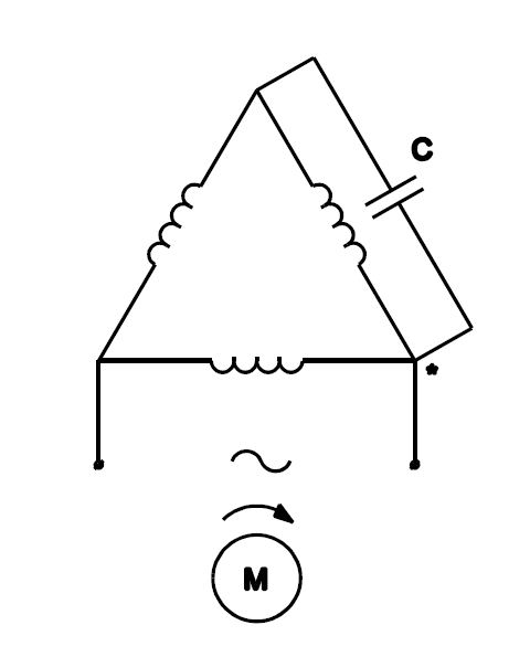
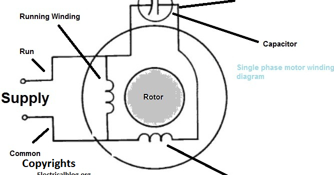
And how to connect the both winding with one another. Generally the ceiling fan motors are split phase single phase ac motors.

Hk 4114 Capacitor Start Capacitor Run Induction Motor Free
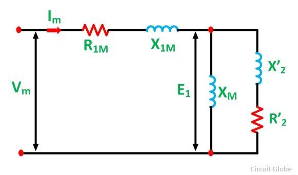
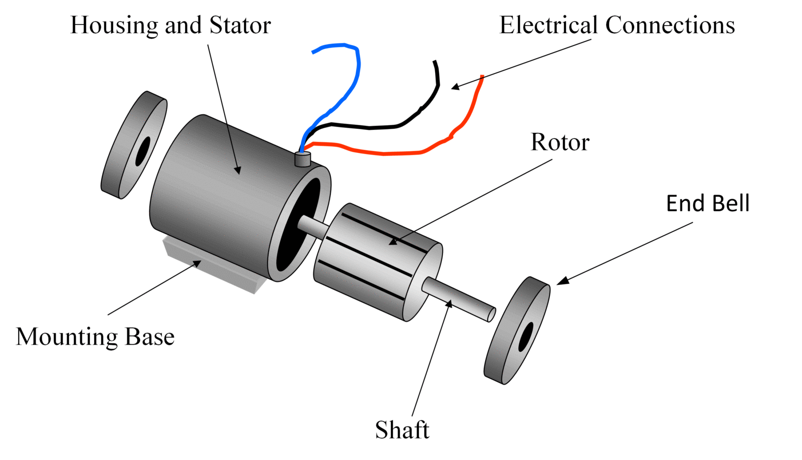
Induction motor wiring single phase. The electric motors that utilize the single phase power supply for their operation are called as single phase motors. The stator contains two types of windings. In the single phase 36 slots winding diagram. A single phase induction motor is similar to the three phase squirrel cage induction motor except there is single phase two windings instead of one three phase winding in 3 phase motors mounted on the stator and the cage winding rotor is placed inside the stator which freely rotates with the help of mounted bearings on the motor shaft. Single phase induction motors a single phase induction motor is an electric motor that operates on a single waveform of alternating current. The main parts of a single phase induction motor are the stator rotor windings.
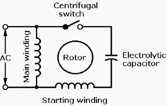
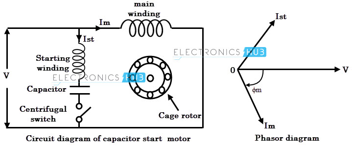
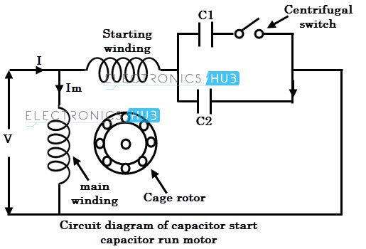
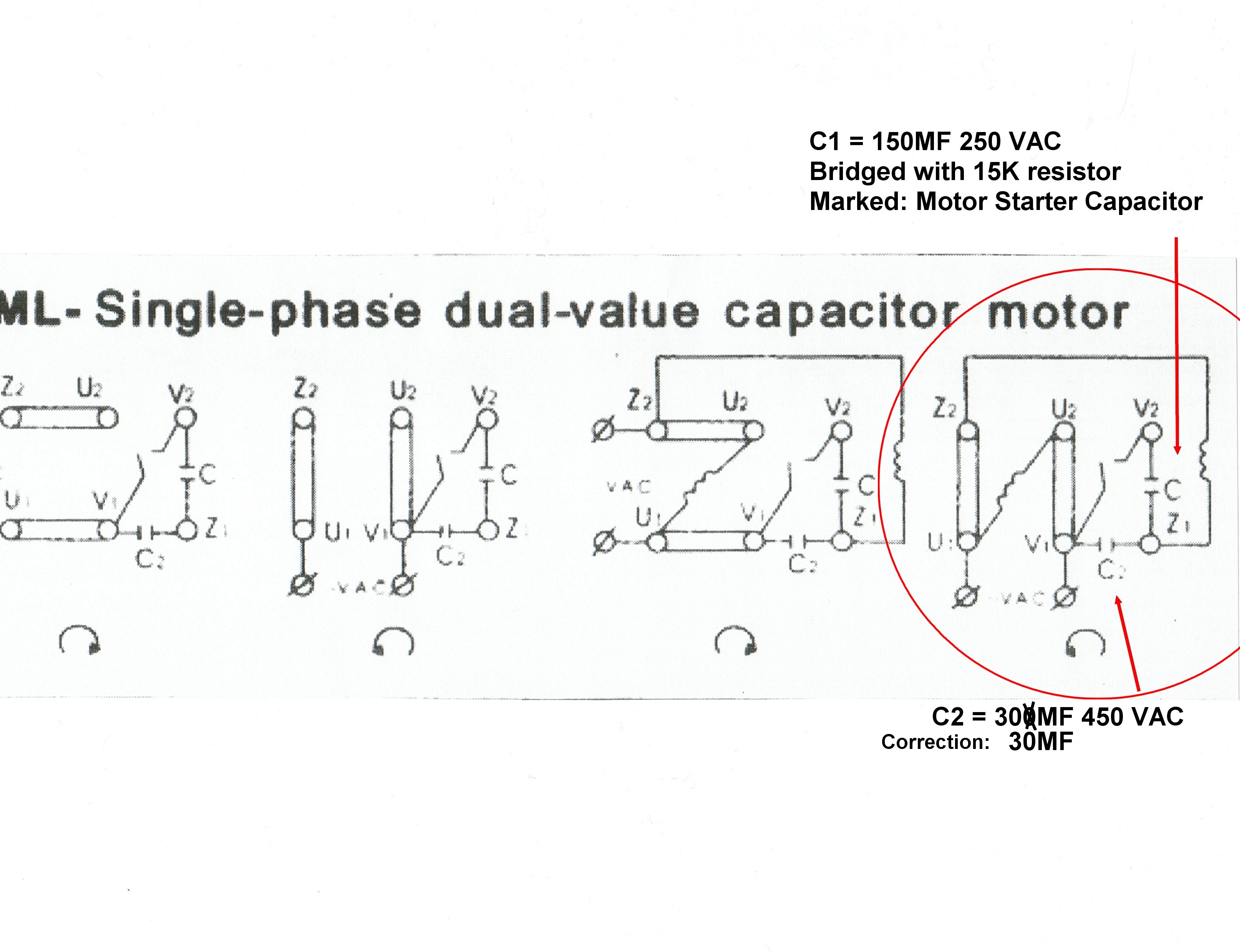
Single phase stator produces a nonrotating pulsating magnetic field. Or single phase motor with centrifugal switch wiring diagram. These are classified into different types but the frequently used single phase motors can be considered as single phase induction motors and single phase synchronous motors. The stator is the fixed part of the motor to which ac. A motor with a start and run capacitor and a start and run coil. This video will show you how to connect a single phase motor with two capacitors.
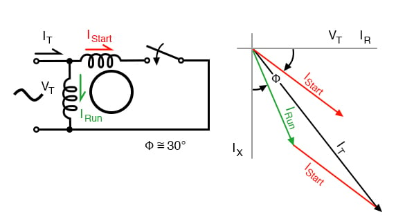
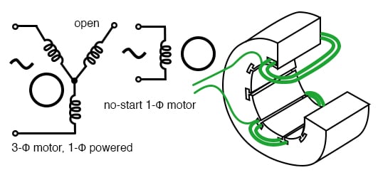
One is the main winding and the other is the auxiliary winding. The single coil of a single phase induction motor does not produce a rotating magnetic field but a pulsating field reaching maximum intensity at 0 and 180 electrical. The main winding and starting or auxiliary winding connection shown. There are two winding inside the ceiling fan known as starting winding and running winding. Single phase induction motors are used in residential applications for ac motor appliances in single or multiple dwellings. This post is about the single phase 4 pole induction motor winding diagram with centrifugal switch.

