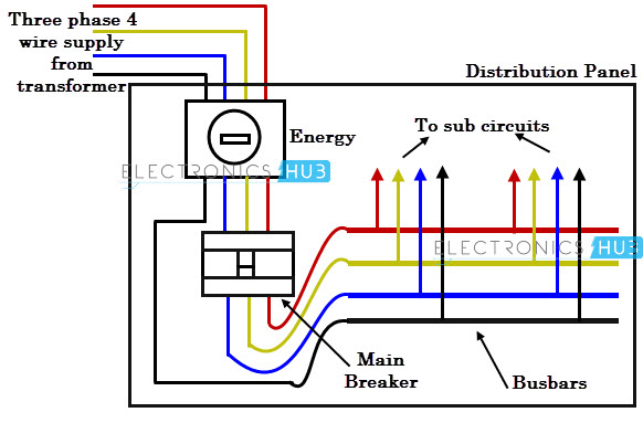
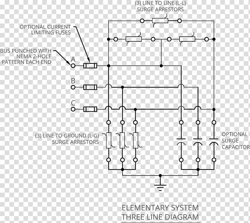
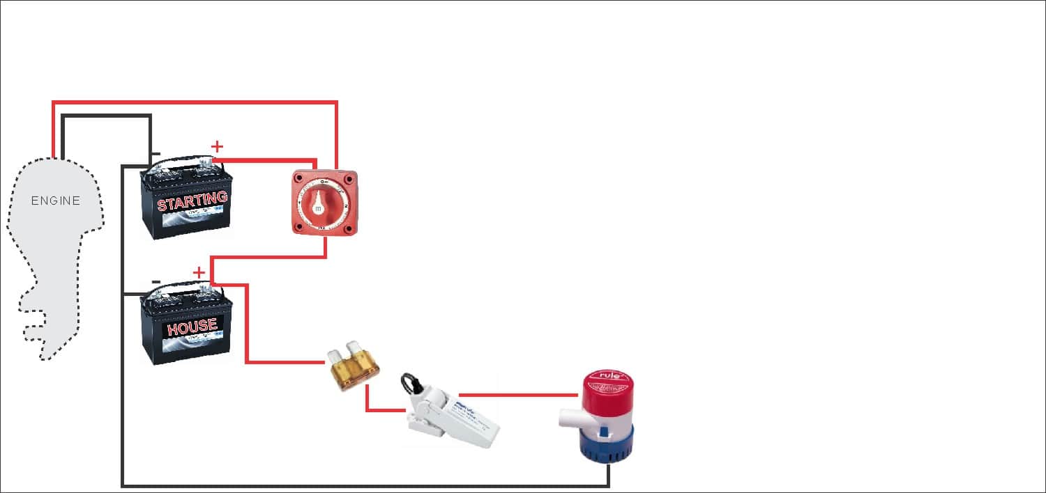
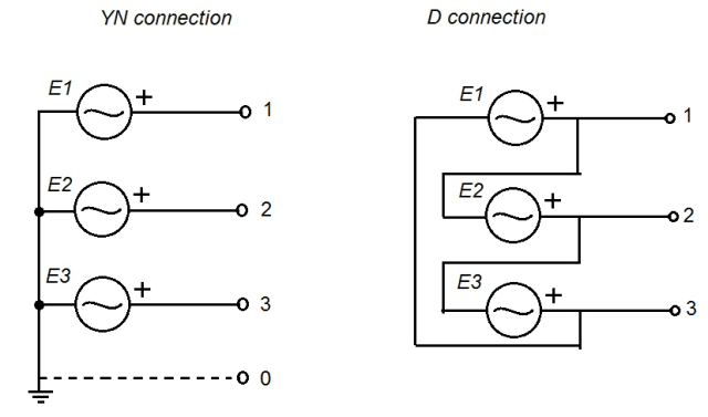
On a three line diagram however you can see the positive negative ground cables of a dc system and l1 l2 l3 on three phase neutral and ground cables on an ac system. Red boxes represent circuit breakers grey lines represent three phase bus and interconnecting conductors the orange circle represents an electric generator the green spiral is an inductor and the three overlapping blue circles represent a double wound transformer with a tertiary winding.

Full House 3 Phase Line Wiring Installation Single Line Connection By Tech Bondhon
Three line electrical diagram. A three line diagram is however a more detailed presentation of an electric system with actual cabling information involving positive negative ground cables for dc l1 l2 l3 neutral and ground cables on an ac system. Single line diagram of power system definition. Industrial single line diagram. What are the difference between single line diagram sld and three line diagram 1three line diagram are prepared as a result of further working on the basis of a sld as they provide details for. It should be of the general magnitude of the components and the choice is arbitrary. We can easily observe three phase circuits by looking at power line while travelling on roads.
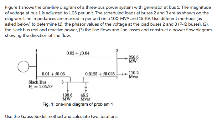
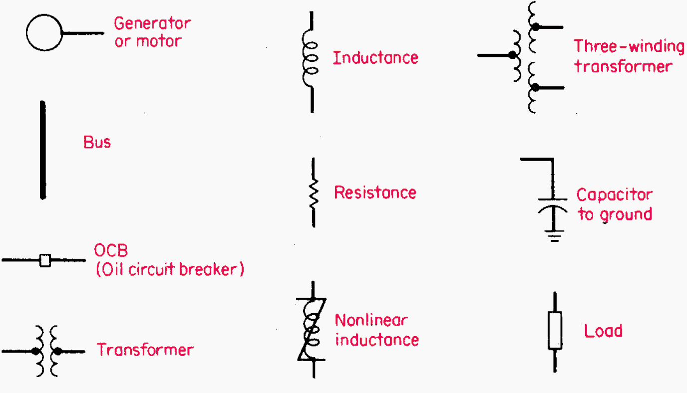
We usually depict the electrical distribution system by a graphic representation called a single line diagram sld. Specifications are given in above table. The single line diagram of a power system is the network which shows the main connections and arrangement of the system components along with their data such as output rating voltage resistance and reactance etc. Three phase power distribution for industrial environment. Each positive and negative line is represented as a single line. Now that you are familiar with electrical symbol lets look at how they are used in interpreting single line diagrams.
In this problem 25000 kva is chosen as the base s and simultaneously at the generator end 138 kv. Rockis 2001 one line diagrams one line diagram a diagram that uses single lines and graphic symbols to indicate the path and components of an electrical circuit. Industries or factories are installed with three phase power in order to connect heavy. Establish base voltage through the system by observation of the magnitude of the components in the system a base value of apparent power s is chosen. A single line can show all or part of a system. Large hotels restaurants most factories office buildings and grocery stores with heavy refrigeration systems have three phase services.
Even for a large power transmission system they are three phase transmission lines unless they are of dc. Figure 1 simple single line diagram. 2three line diagram is a part of the detailed design document. We use universally accepted electrical symbols to represent the different electrical components and their relationship within a circuit or system. The electricity flows from the negative side of the battery through the resistors to the positive side of the battery. 2 line diagrams a line ladder diagram is a diagram that shows the.
Now lets go through a industrial single line. Single line diagram is the representation of a power system using the simple symbol for each component. You can tell by the symbols that this single line diagram has three resistors and a battery. Electrical symbols and line diagrams chapter 3 material taken from chapter 3 of electric motor controls g. To interpret one lines you first need to be familiar with the electrical symbols. Calculation procedure in 8 steps 1.
Below is a simple electrical circuit. Figure 4 single line diagram of electric power system supplying motor loads. 3used for control designing circuit. It is very versatile and comprehensive because it can depict a very complicated three phase system. One line diagrams are used when information about a circuit is required but detail of the actual wire connections and operation of the circuit are not.


