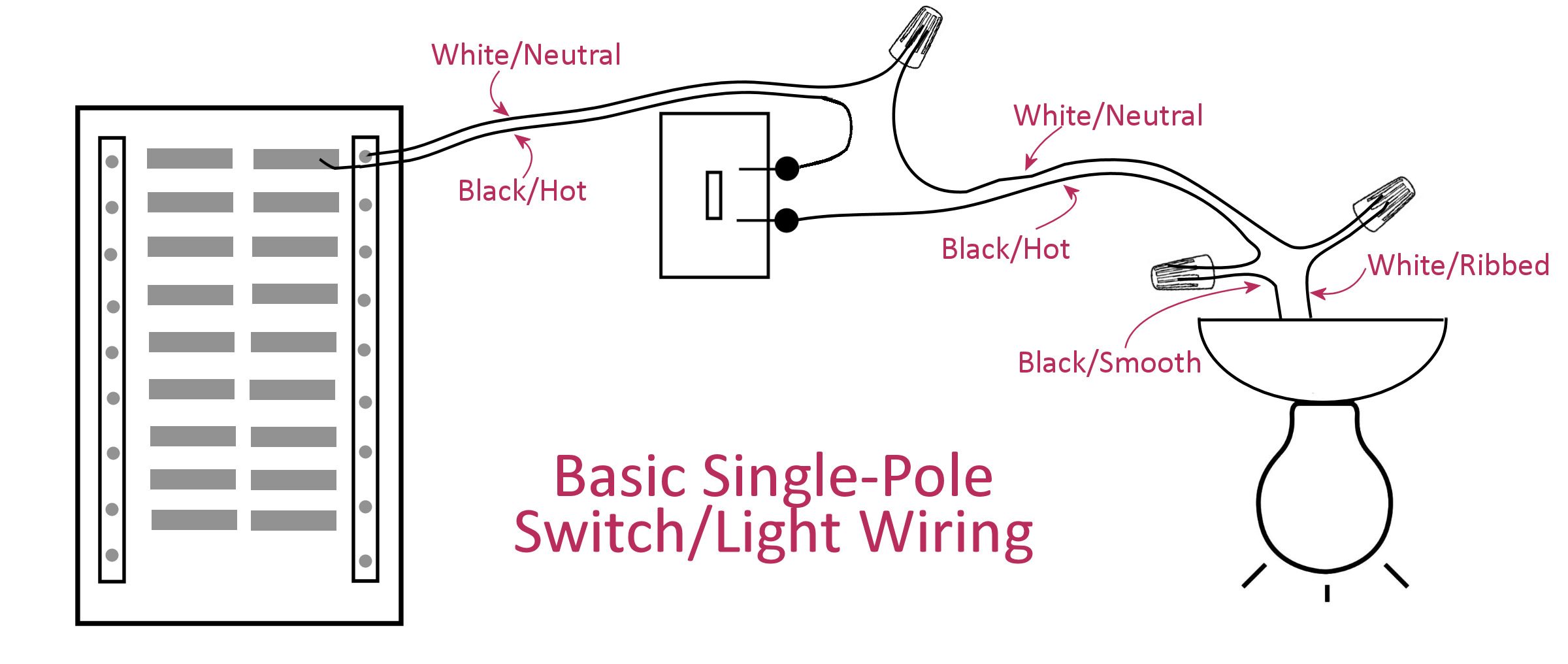
The power source comes from the fixture and then connects to the power terminal. Wiring diagrams for light switches electrical wiring diagrams home electrical wiring diagrams are an important tool for completing your electrical projects.
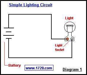
Basic Electricity Tutorial Switches
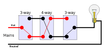
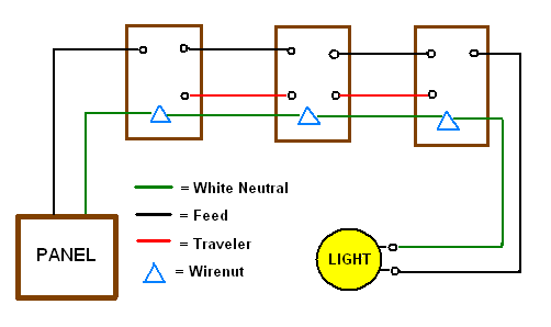
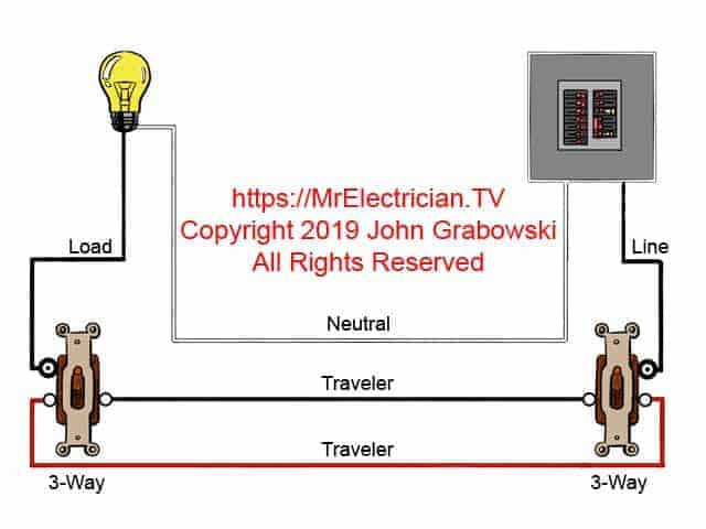
2 switches 1 light wiring diagram. An electrical wiring diagram can be as simple as a diagram showing how to install a new switch in your hallway or as complex as the complete electrical blueprint. Why if you need two switches to operate one fixtureyou install two three way switches the switch comes with a wiring diagram. Wiring diagrams for light switches wiring 3 way switches wiring 4 way switches. Also known as three way switching the job calls for a pair of special three way switches and an appropriate length of 14 3 conductor cable to join the switches together. You will also need to wire with 123wgr this has 4 wires. Light switch wiring diagram 2 switches 2 lights wiring diagram is a simplified agreeable pictorial representation of an electrical circuitit shows the components of the circuit as simplified shapes and the capability and signal friends between the devices.
2 black and 2 white. Explanation of wiring diagram 1. Connect the white wire from the source to the white wire or silver screw on the light fixture. Wiring two light switches. Com on the first switch connects to com on the second switch l1 on the first switch connects to l1 on the second and l2 on the first switch connects to. Once you pull the 14 3 cable and the circuit power source wires from the switch boxes.
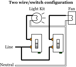
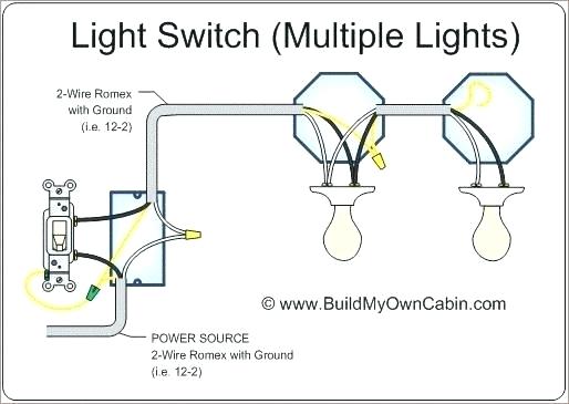
This diagram illustrates wiring for one switch to control 2 or more lights. Cable d fig 2 is a three core and earth this is the 3 wire control that links the two light switches together. The black wire power in source attaches to one of the switch screw terminals. Fixture controlled by two switches. You will see that there is a hot wire that is then spliced through a switch and that then goes to the hot terminal of the light. On both the cable from the source and that leading to the first switch box strip off 1 inch of insulation from each individual wire.
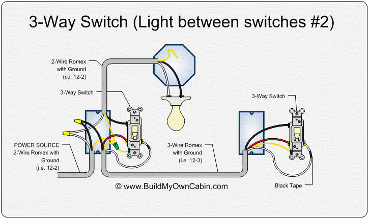
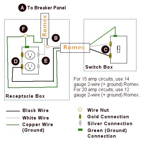
Switch wiring shows the power source power in starts at the switch box. The source is at sw1 and 2 wire cable runs from there to the fixtures. The hot and neutral terminals on each fixture are spliced with a pigtail to the circuit wires which then continue on to the next light. In order to code the white wire which is used as a power wire from the light fixture through the switches black electricians tape is wrapped around the wire in the boxes. Wiring two switches to one light fixture adds convenience to any room with two entryways. Circuit electrical wiring enters the switch box.
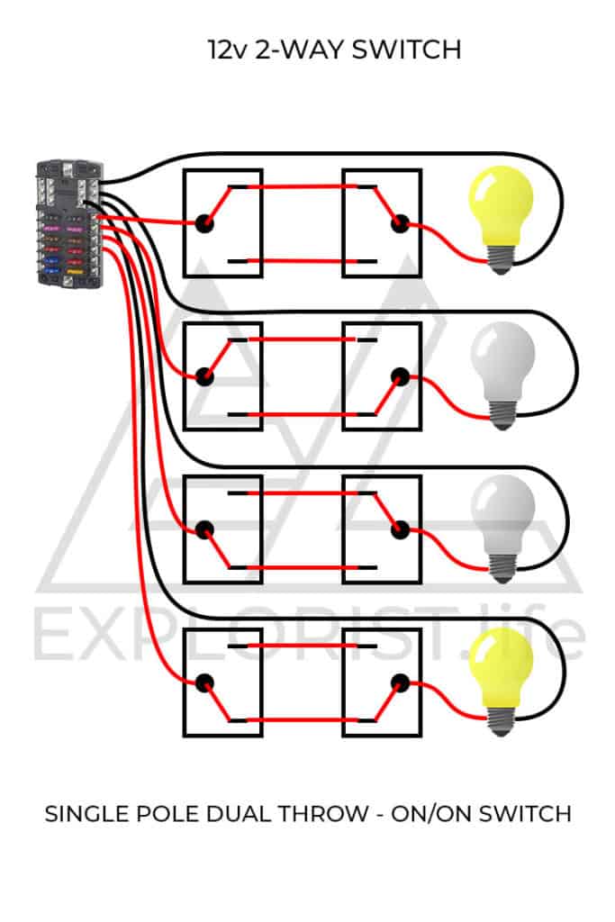
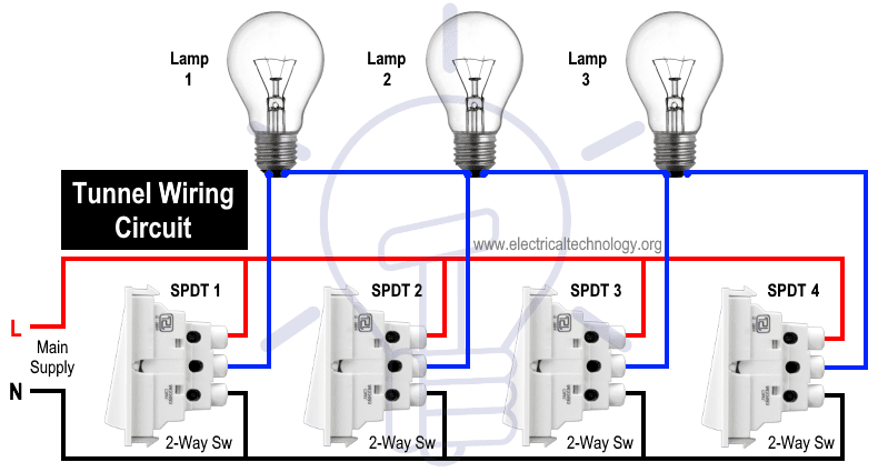
Two way switching schematic wiring diagram 3 wire control. A 2 way switch wiring diagram with power feed from the switch light. The bare ground has no insulation. Power through light two three way switches control one light with the electric power coming through the light on a two wire cable.
