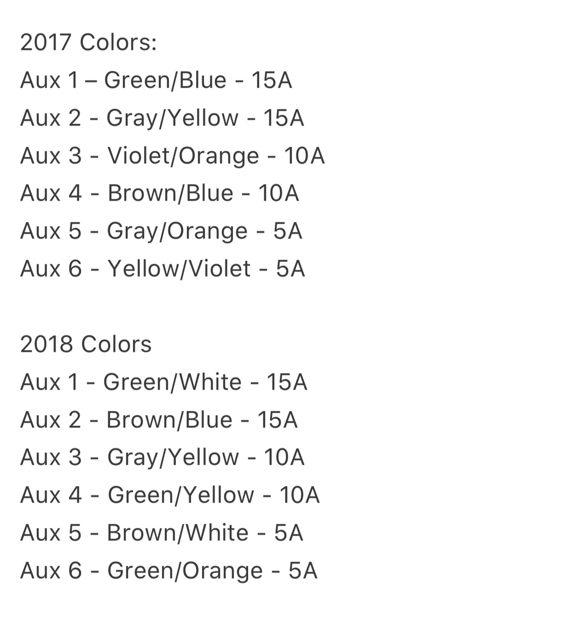
Whichever wire you connected your aux switch wire to is the one that is now energized 12v when the switch is on and the wire you should use to run to your device. If your truck does not have upfitter switches use the light bar manufacturers harness as you normally would but use the larger gauge red wire as the power wire for the 50 light bar use the smaller gauge red wire as the power wire for the cube lights and use the green wire as the power wire for the backglow if applicable.

Wiring Diagram Ford Raptor Diagram Base Website Ford Raptor
2019 ford upfitter switches wiring diagram. The ford upfitter switches are optional instrument panel mount switches option code 66s that control passenger side mounted relays. 2008 ford super duty upfitter switches. Power distribution box diagram. Pull out the one you picked and proceed with your wiring. Passenger compartment fuse panel diagram ford f 150 fuse box diagrams change across years pick the right year of your vehicle. The 2019 ford f 150 has 2 different fuse boxes.
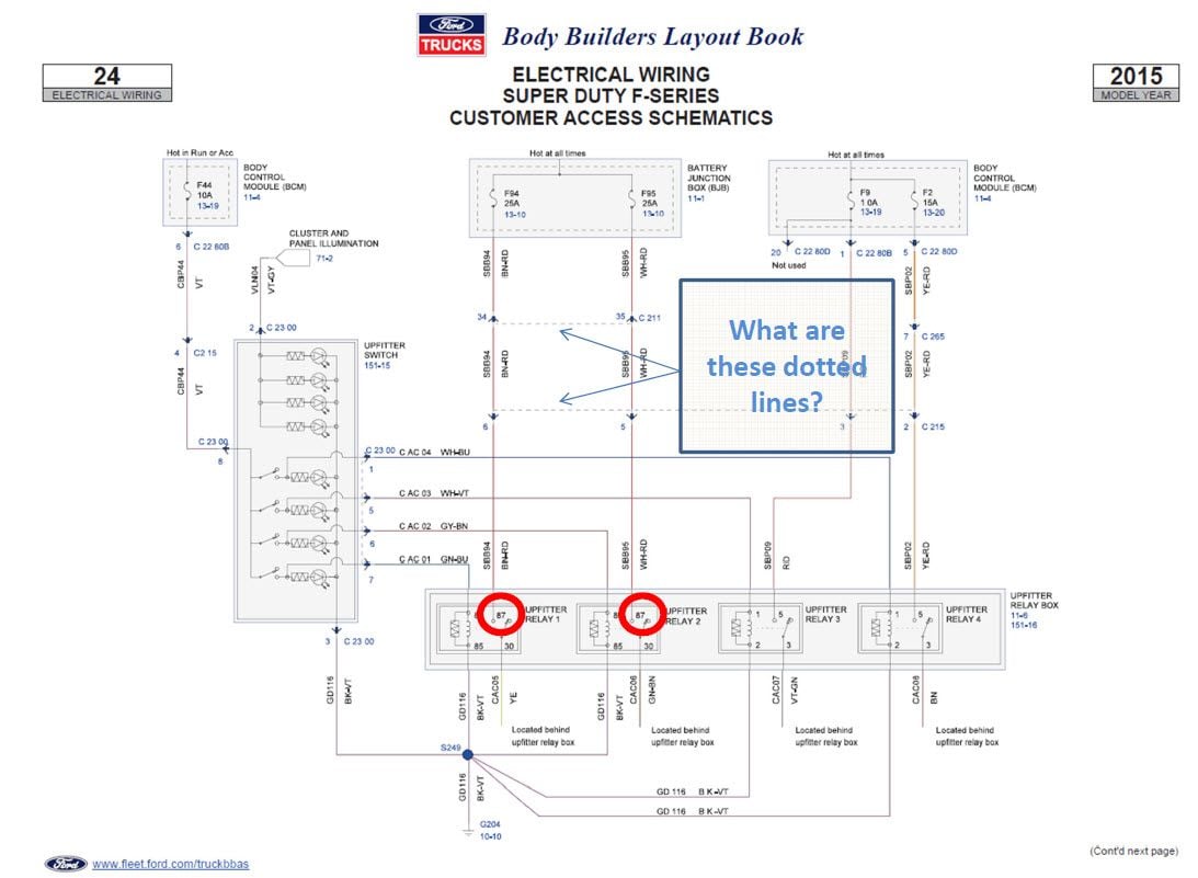
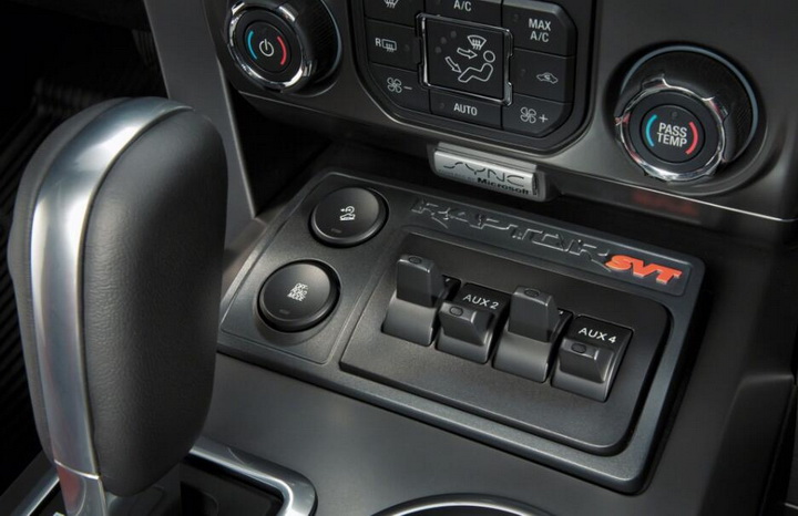
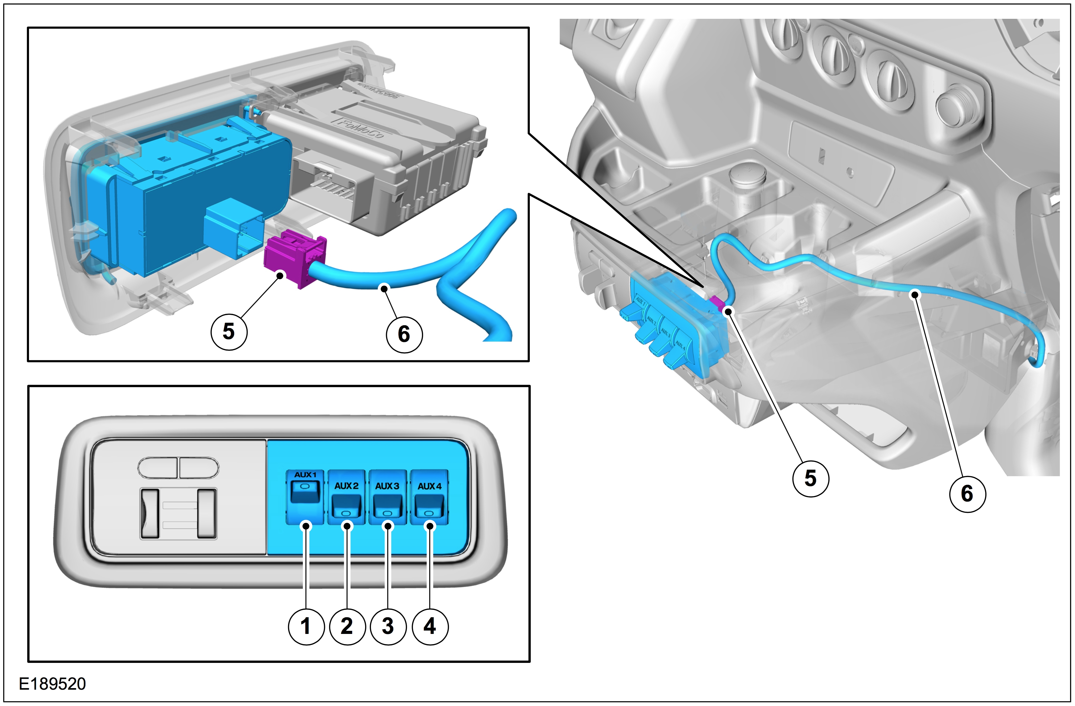
Learn more about being a ford owner here. These relays power four blunt cut wires that are taped on a harness near the relay pack that can be found beneath the instrument panel and to the left of the steering column. Currently available on super duty and coming soon on 2020 transit available fall 2019 2021 e series and 2021 medium duty both available winter 2019. Selectable drive mode switch upfitter switches raptor 36. The hot side is nearest the battery the switch side is nearest the firewall. From the factory the pass through wires are taped to a wiring harness.
To connect the baja designs lights all you do is run the red hot wires to the battery side wires and the redblack to the switch side wires. Ford personnel andor dealership personnel cannot modify or remove reviews. For 2020 upfitters are on passenger side make upfitters hot with key offwatch this video httpsyoutubehgbdaamfjeq how to wire up 2017 and up ford f. This easy to follow video will explain the enhanced upfitter switches and show you how to convert the 40 amp circuits to be powered at all times. This easy to follow video will explain the enhanced upfitter switches and show you how to convert the 40 amp circuits to be powered at all times. You can use a wire nut to connect several together to a single upfitter switch connection.
The upfitter interface module uim is an optional factory installed device that easily allows a direct controller area network programmable logic interface to control devices quickly and.


