3ø wiring diagrams 1ø wiring diagrams m 3 m 3 high speed delta connection low speed star connection w2 or white w2 or white u2 or black u2 or black v2 or orange v2 or orange u1 or red u1 or red v1 or yellow v1 or yellow w1 or blue w1 or blue thermal contacts tb white thermal contacts tb white l1 l1 l2 l2 l3 l3 e e codes. Show comments hunker may earn compensation through affiliate links.

Ga 7315 3 Speed Fan Wiring Download Diagram
3 speed fan wiring diagram. 3 way switched outlet wiring diagram. Black speed switch three wire capacitor. I need a wire diagram for a 3 speed 3 wire switch and diagram of capacitor for a model tfp ceiling fan my guess is the capacitor is connected wrong and that is why i am only getting 2 speeds submitted. Injunction of 2 wires is generally indicated by black dot at the intersection of two lines. For more ceiling fan wiring diagrams check this link. It reveals the elements of the circuit as streamlined forms and the power as well as signal links between the tools.
An initial look at a. The hot wire from the source connects to the common terminal on sw1 and the. Ceiling fan circuit diagrams three speed fan instructions share this article pheori wiley pheori wiley is a freelance writer who has written articles for helium and associated content among others. Click on the image to enlarge and then save it to your computer by. She has been writing professionally since 2003 and has used her knowledge of programming web development and auto repair to share in her writing what she learns from her day to day adventures. A wiring diagram is a simplified standard pictorial representation of an electric circuit.
Ceiling fan wiring diagram 1. 1024 x 960 variety of hunter 3 speed fan switch wiring diagram. Hunter 3 speed fan switch wiring diagram download. And upwards diagram dd5 two speed motors for all other single phase wiring diagrams refer to the manufacturers data on the motor. A novice s overview to circuit diagrams. 18l engine performance circuits 4 speed at 3 of 3 engine control 1zr fe2zr fe toyota corolla cooling fan ecu a41 2 910 a50a b31b engine ecu rhd 13 ae3 lhd 13 ae10 2bd1bd1 1 1 2 110 bb 111 engine control 1zr fe2zr fe 9 p 4 ae5 cpu b can if 5v ic display 20 check engine efi big et 2 11 4s canl 10 4n 32 11 4n 33 30 2b 10 4c 30 12 2h.
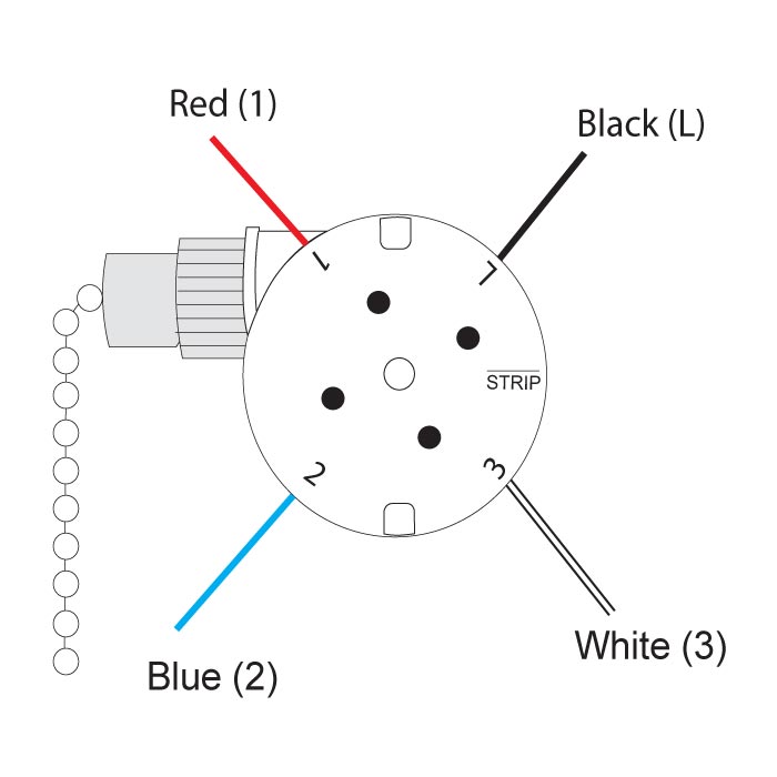
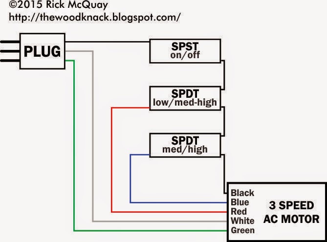
Westinghouse 3 speed fan switch wiring diagram gallery collection of westinghouse 3 speed fan switch wiring diagram. The switch will have a single main input wire known as the line and three additional wires that control speed. This diagram shows the wiring arrangement for a 3 way switched outlet. 1600 x 1236 download. Using the fan manufacturers wiring diagrams as a guide locate the wires for the three speed switch and the fans motor. The motor will also have three speed wires and one neutral wire.
It reveals the parts of the circuit as streamlined forms as well as the power as well as signal links between the gadgets. A wiring diagram is a simplified traditional pictorial depiction of an electric circuit. According to earlier the traces in a hampton bay 3 speed ceiling fan switch wiring diagram represents wires. With this wiring the receptacle can be controlled from two locations. 5 years agoceiling fan speed switch repairhunter fan speed control. With this arrangement the switches control power to the ceiling box and a pull chain is used to control fan speed.
18l engine performance circuits 4 speed at 2 of 3 system wiring diagrams 2002 toyota corolla le page 14 of 41 fig 14. Assortment of ceiling fan wiring diagram 3 speed. Sometimes the wires will cross. How to wire a 3 speed fan switch. The source is at sw1 and 3 wire cable runs between all the devices. However it does not imply link between the wires.


