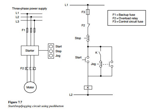
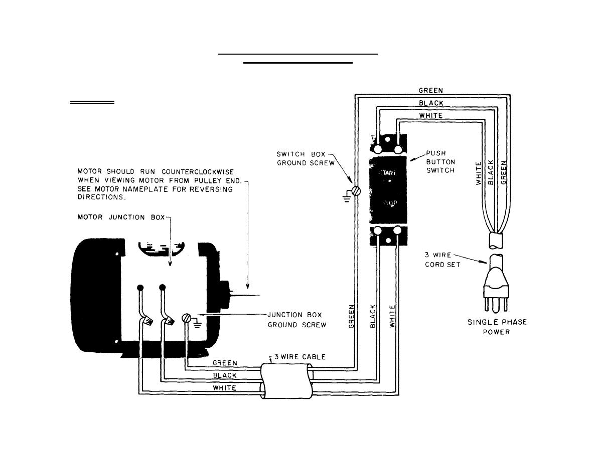
The most common use of 3 wire control is a startstop control. Basic wiring for motor control technical data.

Motor Overload Wiring Diagrams Diagram Base Website Wiring
3 wire motor control circuit. Wiring diagrams show the connections to the controller. Wiring diagrams sometimes called main or construction diagrams show the actual connection points for the wires to the components and terminals of the controller. If the single pole switch is toggle closed the motor starter will start and stay on for as long as the single pole. A simple three wire push button control circuit is shown in figure 18 7. Multi speed 3 phase motor 3 speeds 1 direction power control diagrams. Three phase electrical wiring installation in home iec nec.
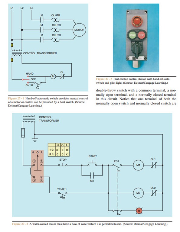
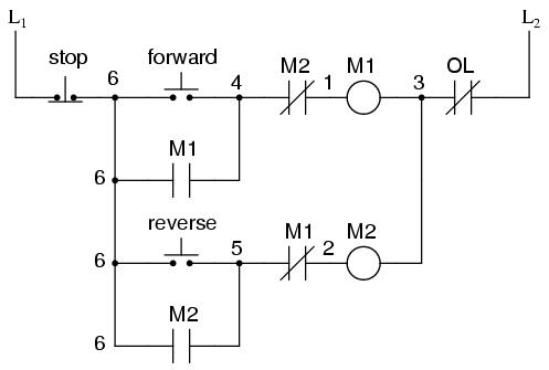
3 easy to build speed controller circuits for dc motors are presented here one using mosfet irf540 second using ic 555 and the third concept with ic 556 featuring torque processing. The circuit shown here provides two direction control forward and reverse for a three phase electric motor. Also explain why there is only one set of overload heaters instead of two one for forward and one for reverse. When push buttons control the operation of a motor three wires are run from the push button control station to the starter figure 18 6. Draw a multiple startstop 3 wire control circuit to control a 3 phase motor from three locationsthis motor is connected to a fan and has overload protection. If the single pole switch marked s1 is left open then the liquid level switch in the circuit will now be the control.
When you press the start button and the stop button is not pressed the 24vdc relay energizes and it pulls in the r1 contactor that feeds three phase power to the motor. See image below for an example of 3 wire control being used to pull in a contactor to start a 3 phase motor. Explain how the reversal of motor direction is accomplished with two different motor starters m1 and m2. One line diagram of simple contactor circuit. The two wire circuit in configuration 2 operates as follows. Three wire control circuits are characterized by the use of momentary contact devices such as push buttons.
A circuit which enables a user to linearly control the speed of a connected motor by rotating an attached potentiometer is called a motor speed controller circuit. How to connect a portable generator to home supply system three methods. Two speeds two directions multispeed 3 phase motor power control diagrams. This video walks you through the basic 2 wire and 3 wire control for 3 phase motor controllers. Include a flow switch in the circuit which will not allow the holding contact to keep the motor starter energized if the airflow switch does not close to prove thr fan is turning.
