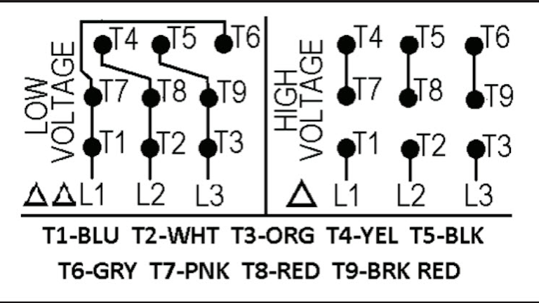
Example nameplate motor. 6 wire motors have three wires per phase.

Ugly S Motor Wiring Diagram 6 Wire Diagram Base Website 6
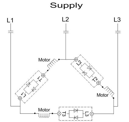
6 wire motor connection. How the wires are interconnected dictates the voltage being supplied to the motor. Measure and record the resistance for all six wires. A three wire three phase circuit is usually more. The motor will supply the same amount of power but with a different load amperage. The diagram below illustrates how the motor is connected in 6 wire also known as inside delta. 240 vac your power supply is 415 vac for more detail please refer my post.
The motor will supply the same amount of power but with a different load. For this example that means we want to connect the orange and blue wires and. I believe i need to wire u1 v1 w1 to power and leave u2 v2 w2 disconnected. Most national instruments stepper motor interfaces do not support 6 wire stepper motors although some motors do not require the center taps to be used and can be connected normally as a 4 wire motor. 3 phase motor wiring diagram 6 wire. To get the delta start for a six lead motor dont connect 4 5 and 6 together.
3wire 6wire connection. Two wire leads connect to either end of one phase with a third wire connected to the center point between the coils as shown in figure 1. Six wire three phase electric motors are dual voltage motors. Now for the purposes. How to wire a 3 phase motor and vfd duration. Below is the motor data plate and whats left of the wiring diagram.
This is commonly used when replacing a stardelta type motor starter. The supply voltage is either 240 volts alternating current vac or 480 vac. An alternative connection is 6 wire or inside delta connection. As your known for star delta starterno cooper bar install at motor terminalthat why it used 6 wirefor other starter used 3 wire with cooper bar at motor terminal. This third wire is commonly referred to as the phases center tap. The standard connection of an electronic soft starter is 3 wire.
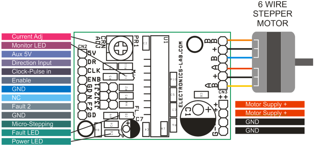
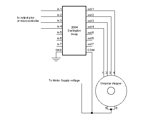
The following illustrates the difference between soft. To connect the motor for unipolar operation the six wires are configured essentially as an h bridge. How to wire a baldor 3 phase motor. 6 wire stepper motor connection diagram wiring diagram is a simplified all right pictorial representation of an electrical circuitit shows the components of the circuit as simplified shapes and the gift and signal links between the devices. 6 wire stepper motor left 8 wire stepper motor in parallel right 8 wire stepper motors. Connect the other motor leads 4 5 and 6 together.
I am trying to wire up a two speed 6 wire 3 phase motor to run at its highest speed. Determine which wires to ignore. The major advantage is that the current in the scr is 58 less than it would be for the same motor connected in 3 wire. Most stepper motors come with four six or eight wires. 415 vac delta connection. Instead connect motor lead 1 and 6 to l1 typically black motor lead 2 and 4 to l2 typically red and motor lead 3 and 5 to l3 typically blue.
Arduino 6 wire stepper motor tutorial step 1.


.png)


