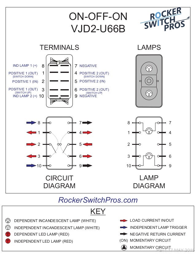
Contact terminal will make contact with switching lever isolated terminal does not make contact with switching lever contact terminal switch lever bulb notes. Each of our carling rocker switch bodies have the generic wiring diagram loaded into that products own page see photo right.

Carling Switch Diagram 7 Pin Rocker Switch Wiring Diagram
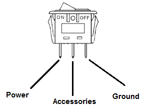
Carling rocker switch wiring diagram. According to previous the lines in a carling switches wiring diagram represents wires. Many of these switches though are quite flexible thought. It reveals the elements of the circuit as streamlined shapes and the power and signal connections between the gadgets. Therell be main lines that are represented by l1 l2 l3 and so on. Wellborn assortment of carling technologies rocker switch wiring diagram. At times the cables will cross.
At times the wires will cross. Standard switch wiring diagrams carling technologies inc. March 11 2019 by larry a. With independent lamp circuit only 3. With lighting sequences 10 20 30 4050 only. However it does not imply link between the wires.
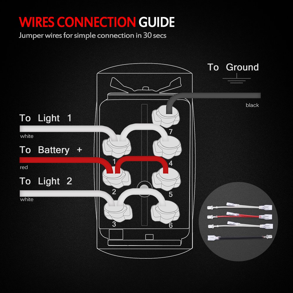
With just a few small jumpers our switch selection can be used for a multitude of different functions. A wiring diagram is a simplified standard photographic depiction of an electrical circuit. Injunction of 2 wires is generally indicated by black dot on the junction of 2 lines. But it does not imply connection between the cables. This rocker is perfect for an engine offrunstart switch. The wiring diagram below will demonstrate how to to wire and power this 12v 20amp on on off 3 way carling contura rocker switch.
It is off at the bottom on in the center and momentary on at the top. With nbl bracket only 2. Injunction of 2 wires is usually indicated by black dot on the intersection of 2 lines. As stated earlier the lines in a carling switch wiring diagram represents wires. There will be main lines that are represented by l1 l2 l3 and so on.


