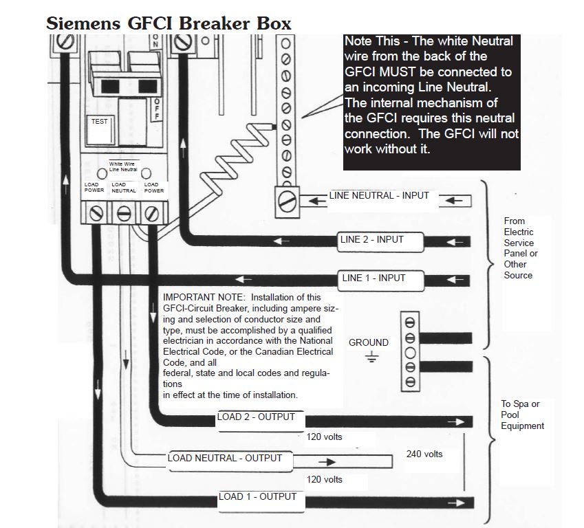
Some units automatically reset when cool others must be manually reset. The hot wire for a branch circuit is connected to the breaker by a set screw on the base.
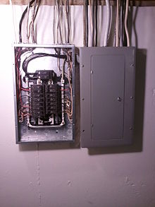
Distribution Board Wikipedia
Circuit breaker panel wiring diagram pdf. Fiber optic cable electrical connections boundary seal to be in. Transformers to step down ac supply voltages to lower levels. Without a ground current cannot flow. Fuses or circuit breakers will cause power to fail if too much current is drawn. Panel wiring diagram 12 label sets 27 bep marine 13 tarndale grove albany auckland nz. Breaker panel wiring diagram wiring diagram breaker box wiring diagram.
Terminals to connect devices. The electrical design for each machine must include at least the following components. I lost power to the front tv double plug too but theres a single. With this manual youll be able to see how every. Wiring diagram book a1 15 b1 b2 16 18 b3 a2 b1 b3 15 supply voltage 16 18 l m h 2 levels b2 l1 f u 1 460 v f u 2 l2 l3 gnd h1 h3 h2 h4 f u 3 x1a f u 4 f u 5 x2a r power on optional x1 x2115 v 230 v h1 h3 h2 h4 optional connection electrostatically shielded transformer f u 6 off on m l1 l2 1 2 stop ol m start 3 start start fiber optic transceiver class 9005 type ft fiber optic push button selector switch limit switch etc. The light xtures in the hall are controlled by these switches.
3 circuit breakers it is very important to note that the primary function of the circuit breaker. Panel a circuit breaker number 13. Circuit breaker basically a reusable fuse a circuit breaker will heat and open if too much current flows through it. This diagram illustrates some of the most common circuits found in a typical 200 amp circuit breaker service panel box. I discovered another j box as you describe with the false panel in the wall behind the shower that is next to the kitchen slide area. Weve been hit with heavy rain and winds for the past few days so i dont want to bring the slide in yet with it being so wet.
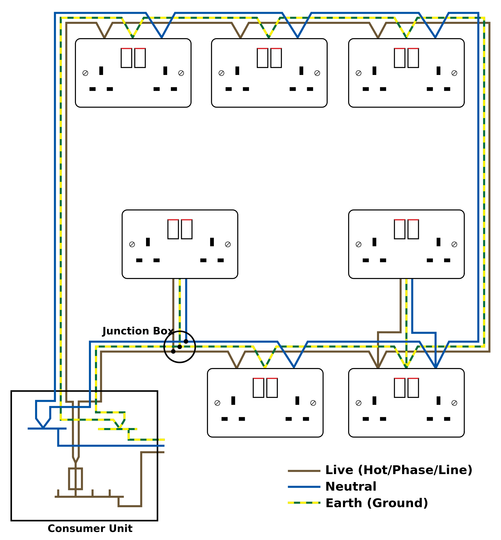
This j box has no power to any of the wiring contained with in it. Power contacts to manually enabledisable power to the machine with e stop buttons. Voltmeter frequency meter circuit breaker 3p 1600a panel light selector switch il1 il2 v symbol designation a acammeter as change over switch ammeter to engine wiring diagram tb3 pc e 11 ac and dc electrical systems on boats 115523 the generator neutral shall be grounded at the generator see diagram 2 or. Electrician circuit drawings and wiring diagrams youth explore trades skills 7 figure 7common electrical symbols. Theres an access hole for it but it looks like i can only get at it with the kitchen slide in. The small number 3 beside the switch symbol indicates a three way switch which means that the hallway lights can be controlled from two dierent locations.
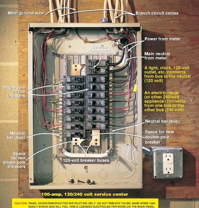
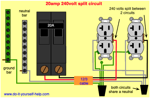
Toyota wiring diagrams. In an industrial setting a plc is not simply plugged into a wall socket. Connectors male connectors typically have extended pins which engage sockets in the female connector. 64 9 415 7261 fax. Circuit breaker panel box wiring diagram. The neutral and ground wires for the circuit are connected to a bar along the side of the service panel box.
The breakers are installed in a panel so that contact is made with one of two hot bus bars running down the middle of the box. Ground the point at which wiring attaches to the chassis thereby providing a return path for an electrical circuit. Circuit drawings and wiring. Wiring diagram arrives with several easy to stick to wiring diagram guidelines. These directions will be easy to understand and apply. Electrical wiring diagrams of a plc panel.
Its meant to assist each of the typical user in building a suitable program. Figure 6floor plan of a typical suite showing power and lighting details.
