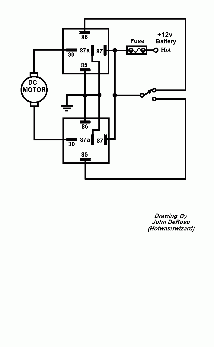
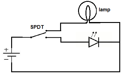
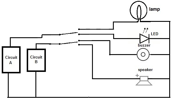
Below is an example of a circuit which utilizes a double pole double throw switch. Sp and dp refer to single pole and double pole st and dt refer to single throw and double throw.

Red White Selectable Marine Led Strip Lights
Dpdt switch wiring diagram. If the humbucker has an alternate or inside out wiring coil b is then the active coil during coil cut. Functions like two separate spdt switches operated by the same actuator. Many people attempting to find info about dpdt toggle switch wiring diagram and certainly one of them is you is not it. Collection of 6 pin dpdt switch wiring diagram. Dpdt toggle switch wiring diagram thank you for visiting our site. We will now go over the wiring diagram of a dpdt toggle switch.
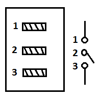
Terminals 3 and 4 represent the toggle switch. Pole refers to the number of circuits controlled by the switch. What do spst spdt dpst and dpdt mean. Dpdt toggle switch wiring. Double pole double throw switch dpdt circuit. Nowadays were pleased to declare we have discovered a very interesting content to be discussed that is dpdt toggle switch wiring diagram.
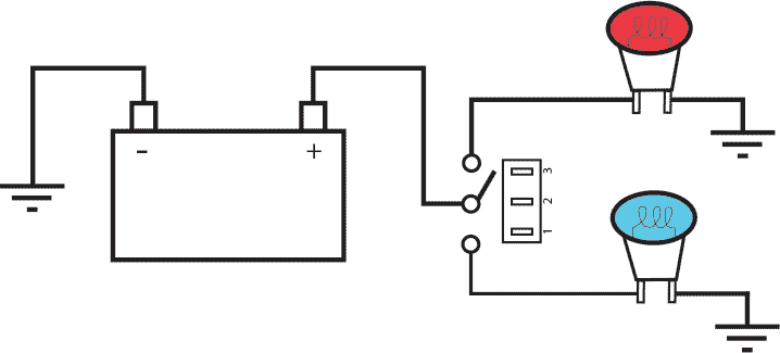
Sep 8 this dpdt illuminated rocker switch has two dependent lamps one top. Carling switches wiring diagram 4 pin carling switch wiring diagram arb carling switch wiring diagram carling dpdt rocker switch wiring diagram every electric arrangement consists of various diverse pieces. This is how you wire a double pole double throw dpdt switch. A wiring diagram is a streamlined conventional photographic depiction of an electrical circuit. Sp switches control only one electrical circuit. Spdt center off switch you can choose series humbucker coil a coil b all with one switch the diagram on.
A double pole double throw switch is actually two single pole double throw spdt switches. When the dpdt switch is switched one way flipped upward in the diagram the lamp and buzzer are both on while the led and speaker are off. Each part should be set and linked to other parts in particular way. Dp switches control two independent circuits and act like two identical switches that are mechanically linked. Terminals 3 can flip between terminals 1 and 5. Switch diagrams illustrate the most common types of toggle and rocker switch.
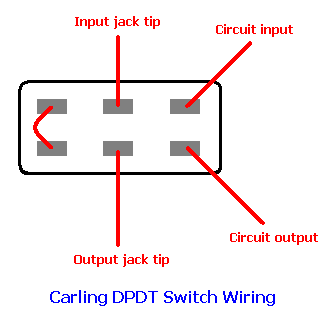
If not the arrangement wont function as it should be. In this video i give you the characteristics of a dpdt switch and how to wire. Toggle switch wiring inside dpdt toggle switch wiring diagram image size 588 x 312 px and to view image details please click the image. 2 methods are explained with associated wiring diagrams. A dpdt toggle switch has 6 terminals. When the dpdt switch is switched.
Below is the schematic diagram of the wiring for connecting a dpdt toggle switch. It shows the elements of the circuit as streamlined forms and the power as well as signal links in between the gadgets. Dpdt plus spst switch using an spst switch connected to the jumper of a dpdt seriesparallel switch works the same way as in the previous diagrams. When the coil cut switch is on a conventionally wired humbucker grounds out the middle wires and coil a is the active coil. Here is a. Dpdt momentary winch switch wiring diagram.
Aug 3 it came with a handheld unit with a rocker switch so up goes up down goes examples in here that can easily be adapted telemecanique wiring diagrams with dpdt control switches you could add a relay at each control. So if a fan is connected to terminal 1 and a motor is connected to. To be able to make sure that the electric circuit is constructed properly. Hi there i hope some one can help i am trying to sort out some controls for a wheelchair i am building i have sorted out all the actuators to run from separate rocker switches 4 x 6 pin dpdt they are powered from the on board 12v batteries 2x 24volts what i want to do is try to find a way i can wire up several actuators the same ones i need with separate controls too so i can press one button and have the seat riser the foot rests and the strand function all work from the one dpdt. You can see above how a double pole double throw switch can allow a circuit to be in 1 of 2 modes. These terminals receive the power necessary to drive the loads on terminals 1 and 5 and 2 and 6.


