Checking the motor and capacitor connections. Anything else we should know to help you best.
Emerson Fan Schematic Pre 1950 Antique Antique Fan
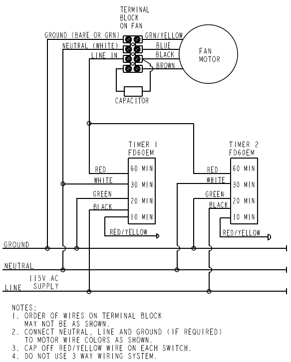
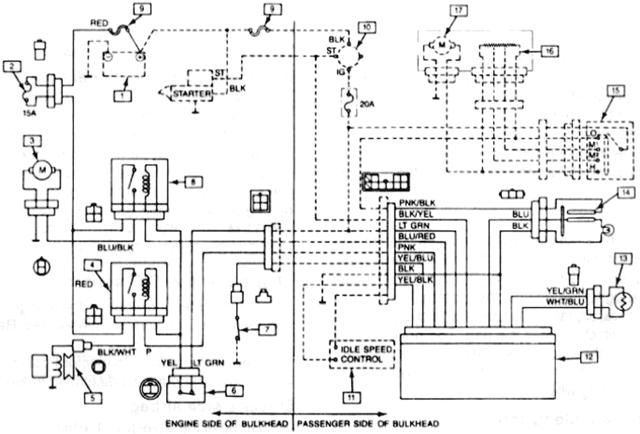
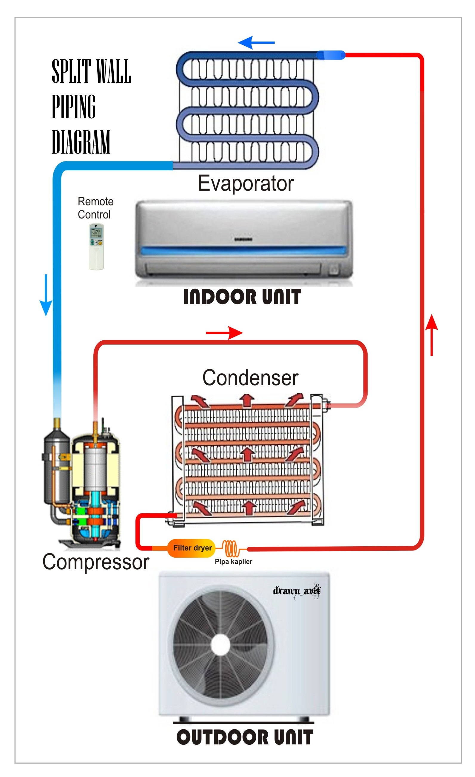
Fan motor wiring diagram. Finally this guide is intended to be used as a general overview of common condenser unit wiring schematics. Each component ought to be placed and linked to different parts in particular manner. Double check your connections using the fan wiring diagrams. Ac how to wire 1 phase 3 speed motor electrical. Some condenser fan motors wire to a circuit board while others use proprietary plugs for their connectors. For a visual picture of typical wiring configurations reference the following guide.
We strongly recommend referring back to your units manual for proper wiring instructions. It shows the parts of the circuit as streamlined forms and also the power as well as signal connections in between the devices. Using this guidebook you will be capable to see how each part needs to be related and also the actual actions you should get in order to effectively total a specific job. The switch will have a single main input wire known as the line and three additional wires that control speed. Here a simple spst switch is used to supply power or not to the fan motor and a regulator is used to controlling the fan speed. This is a simple illustrated circuit diagram of ceiling fan.
Condenser fan motor wiring inspectionnews re. It is supposed to help each of the typical person in building a correct system. The problem was the original motor was a four unit and the brown wires went to it 2 prong capacitor and the black to the board and the orange to the contact. More about electrical. We replaced the fan motor and capacitor. To be noted that the wiring diagram is for ac 220v single phase line with single phase ceiling fan motor.
If not the arrangement wont work as it should be. The motor will also have three speed wires and one neutral wire. Variety of fasco fan motor wiring diagram. How to eliminate 2 run ac fan motor wiring diagram. Using the fan manufacturers wiring diagrams as a guide locate the wires for the three speed switch and the fans motor. The concern is that there is a capacitor for the motor.
So im thinking that the motor may have to start with the slower speeds first. Single phase motor wiring diagram with capacitor baldor single phase motor wiring diagram with capacitor single phase fan motor wiring diagram with capacitor single phase motor connection diagram with capacitor every electrical arrangement is made up of various unique pieces. Wiring diagram comes with several easy to follow wiring diagram guidelines. A wiring diagram is a simplified traditional pictorial representation of an electrical circuit. Single phase motor wiring with contactor diagram the above diagram is a complete method of single phase motor wiring with circuit breaker and contactor. You should see that there is a separate motor winding for high speed.
3ø wiring diagrams 1ø wiring diagrams diagram er9 m 3 1 5 9 3 7 11 low speed high speed u1 v1 w1 w2 u2 v2 tk tk thermal overloads two speed stardelta motor switch m 3 0 10v 20v 415v ac 4 20ma outp uts diagram ic2 m 1 240v ac 0 10v outp ut diagram ic3 m 1 0 10v 4 20ma 240v ac outp uts these diagrams are current at the time of publication. How to verify fan motor wiring connections. Share on facebook. And not start in the high speed because the motor or capacitor has not been designed for that type of operation. Hvac condenser fan motor wiring diagram. Share on twitter.
Ask your own hvac question. The lennox motor said the black goes to the capacitor but in all the diagrams it shows the purple wire goin to the capacitor. Condenser fan motor wiring originally posted by jerry peck see attached photo arrow is pointing to liquidtight flexible non metallic conduit used to route the fan wiring across under the protective grille and above the fan blades. These directions will be easy to grasp and use.

