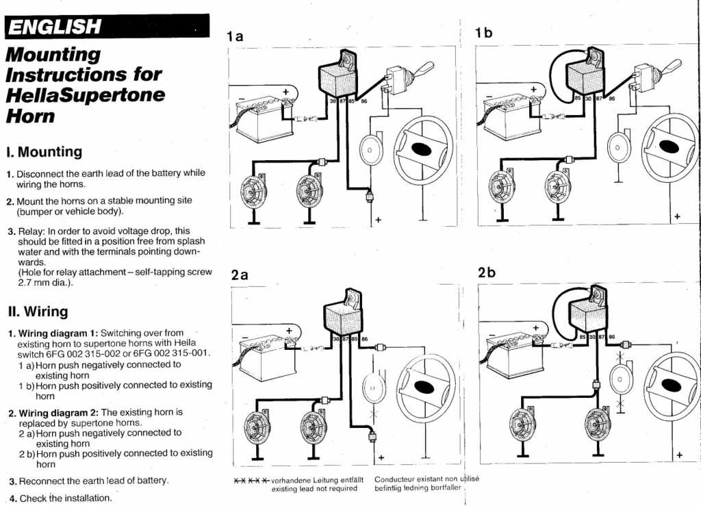
Hella relay wiring. The first fully electronic flasher unit 1968 l relay.

Wiring Horn Without Relay Keju Anb12 Vmbso De
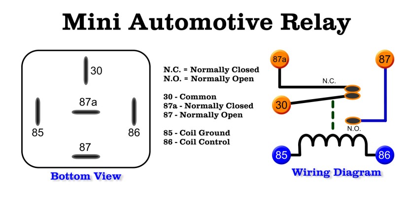
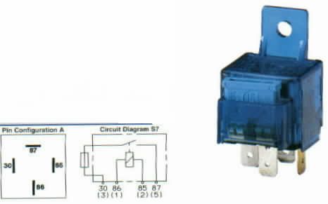
Hella 5 pin relay wiring diagram. Here is a video on how you can test a relay with or without a diagram. Four pin relays do not use this terminal see reference 2 under the common pin designations chart. Truly we also have been realized that relay 5 pin wiring diagram is being one of the most popular topic at this time. This video covers both 4 and 5 pin 12vdc relays. 4 5 1951 first hot wire flasher unit 1960 a relay with metal housing. I cover 34 and 5 pin relays and all you need is a 12v source a multimeter and a test light.
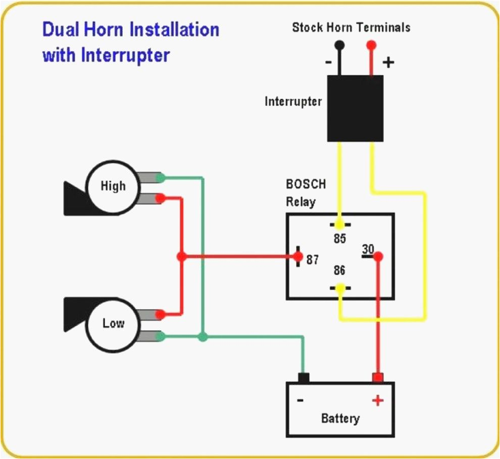
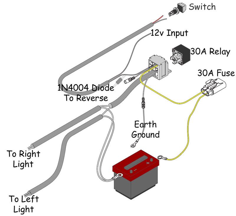
Trailer wiring diagram electrical circuit diagram electrical wiring diagram diy electronics electronics projects light switch wiring boat wiring car horn car audio installation. Wiring diagram hella 4rd 931 680 01 schematron how to wire a hella 12v relay it still runs relays and relay devices products and applications hella hella light relay wiring diagram database relais produkte und anwendungen hella relays electrics catalog hella relays hella ignition and start switches hella hella starter relay carid 12 volt relay wiring diagram free wiring diagram. Multimeter used in video. The first modular system 1969 wipewash interval control unit 1970 k relay. Click on the image to enlarge and then save it to your computer by right. Bosch horn relay wiring diagram 4 pin relay wiring diagram with relay 5 pin wiring diagram image size 640 x 480 px and to view image details please click the image.
Best relay wiring diagram 5 pin bosch endearing enchanting blurtsme. So that we attempted to obtain some terrific relay 5 pin wiring diagram picture to suit your needs. To ensure a maximum relay lifetime the contact material is selected in line with the most demanding quality. Items you will need. The electro mechanical plug in relay has been one of hellas core products for many years. Hella relays feature diodes or resistors to suppress interrupting voltage peaks in the relay coils and thus prevent interference voltage.
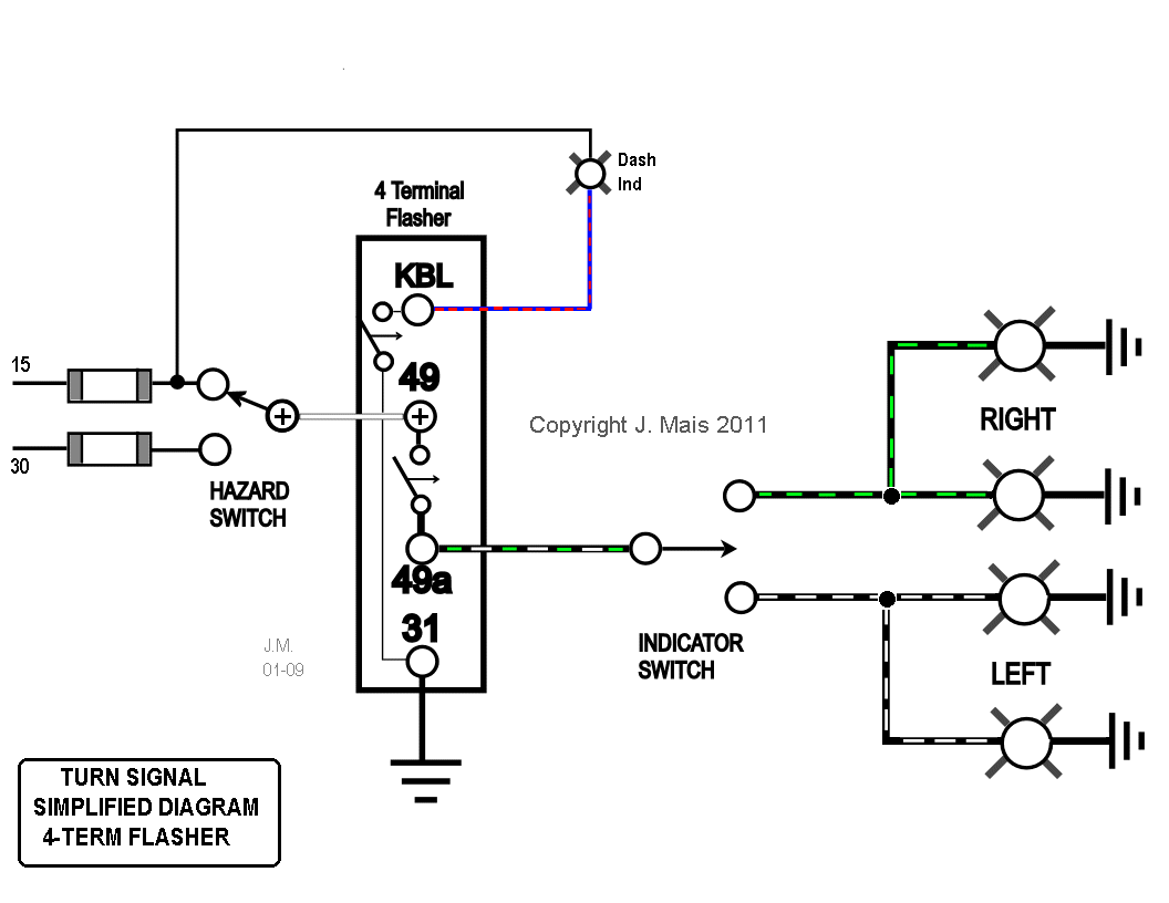
As switch amplifiers used to control electrical loads in plug in standard models these electronic components can be controlled by control units. 12 volt relay wiring diagram bosch relay wiring diagram 5 pole fresh 5 pin relay wiring diagram inspirational pin relay wiring. Adjustable control time delay unit delay on release 12v. Mechanical threshold voltage controller for windshield wipers 1965 e relay. Current controlled relay for direction indicator lamps bi stable relay for switching between low and high beam. In this video i show you how to wire a 12 volt automotive bosch style relay.
Electrical symbols electrical diagram electrical projects electrical wiring custom vw bug car door lock go kart plans car audio installation electronics basics. Wiring diagram database. Saved by robert romero. About the author. This article was written by the it still works team copy edited and fact checked. Assortment of 12 volt relay wiring diagram.
Hella relay wiring diagram starter. Slide this wires wire terminal onto a hella five pin relays terminal labeled 87a this terminal turns hot when the control circuit deactivates. Adjustable control time delay unit delay on release 24v. People also love these ideas.


