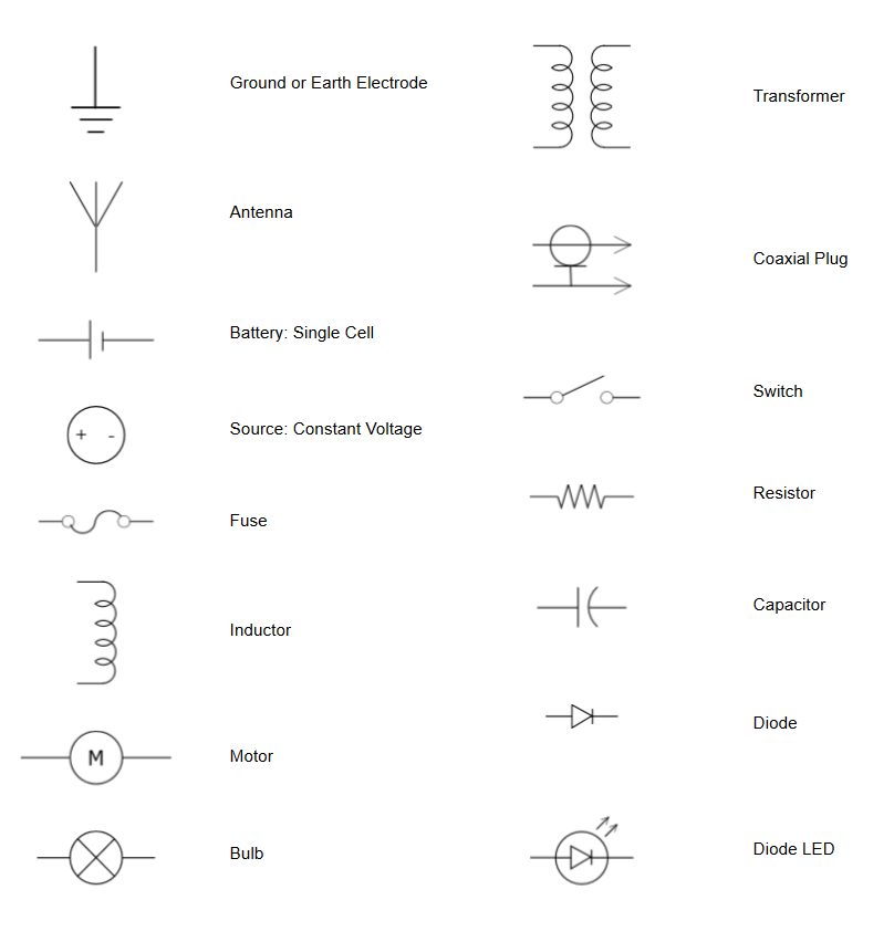
They are usually represented by zig zag lines with two terminals extending outward. Then well talk about how those symbols are connected on the schematics.
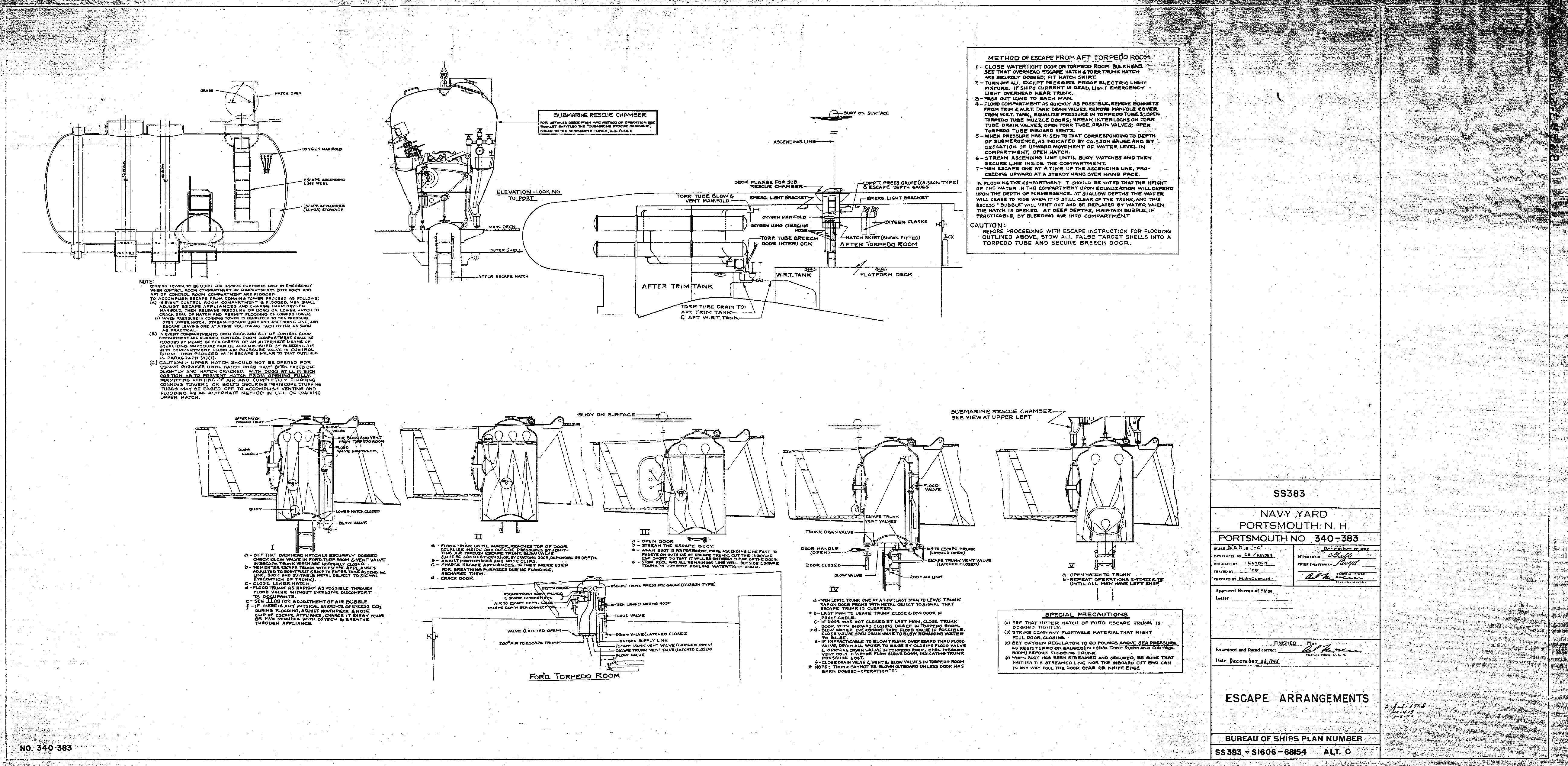
Navy Documents
How to read electrical blueprints pdf. Name designators and values one of the biggest keys to being schematic literate is being able to recognize which components are which. The user can follow the same path. Alphabet of lines 53 3. Basics 8 aov elementary block diagram. Basics 11 mov schematic with block included basics 12 12 208 vac panel diagram. Learn reading pattern read schematics in the pattern that you would read the text.
Basics 10 480 v pump schematic. The signal generated or used by the circuit will flow in this direction. The ability to read construction plans will not only increase your value to your current employer but is a staple to anyone serious about advancing their career as a professional contractor. Blueprint reading fundamentals print. Blueprint reading fundamentals blueprint reading fundamentals course outline topic page 1. In addition to the symbol each component on a schematic should have a unique name and value which further helps to identify it.
How to read a electrical drawing 1. But you can also use the. With rare exceptions schematics should be read left to right and top to bottom. To read electrical schematics the fundamental electrical schematic symbols should be understood. Threads and fasteners 131 6. In our beginners guide.
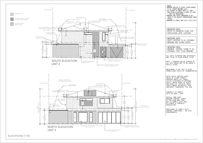
Basics 7 416 kv 3 line diagram. The component symbols tell half the story but each symbol should be paired with both a name and. Basics 9 416 kv pump schematic. Then the de signer defines and designs each component such as general office areas specialized machinery and power distribution equipment. Buildings contain a number of electrical systems these plans include specific electrical designs and additional documentation to verify that the design conforms to all required building codes. Learning how to read construction plans is an essential skill for building a career as a construction worker.
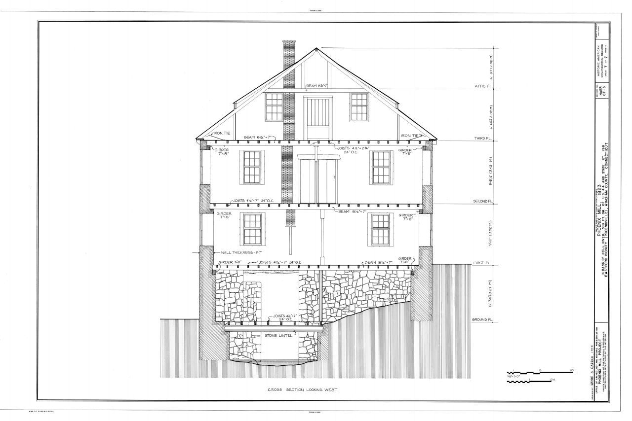
Blueprint reading fundamentals. Section views 117 5. Multiview drawings 89 4. Such as ms office visio pdf etc. Feel free to export print and share your diagrams. Basics 4 600 v 1 line.
A diagram that represents the elements of a system using abstract graphic drawings or realistic pictures. Basics 5 480 v mcc 1 line. The language of. Electrical basics sample drawing index basics 1 overall plant 1 line. In general symbols should share a fair amount in common with the real life components they model. Basics 13 valve limit switch legend.
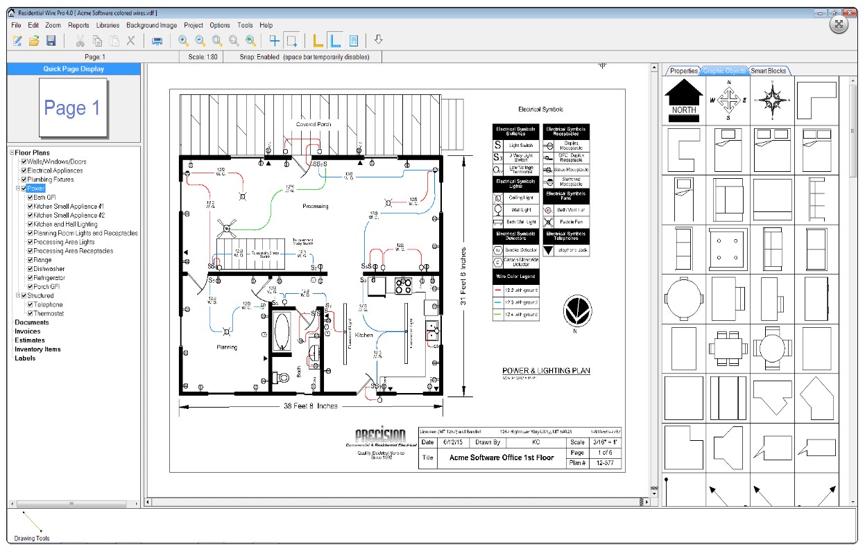
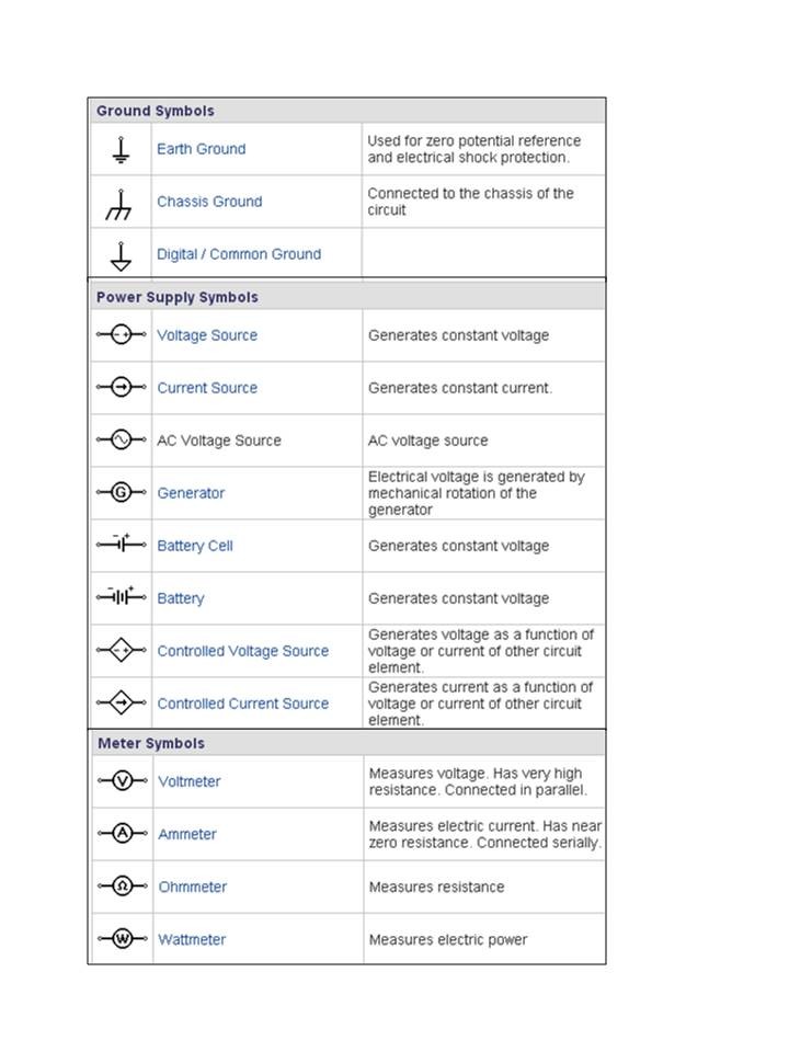
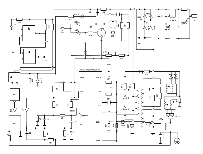
An electrical design goes through several impor tant stages of development. Basics 3 416 kv bus 1 line. Recognizing electrical schematic symbols here are some of the standard and baisc symbols for various components for electrical schematics. Familiarize with standardized electrical symbols. Free download free download free download. A diagram that uses lines to represent the wires and symbols to represent components.
Construction drawings vary from simple to very complex so understanding how to interpret the drawings is crucial for completing the project efficiently and accurately. Resistors are the fundamental components of electrical schematics. Basics 14 aov. Literate in schematic reading. Basics 6 72 kv 3 line diagram. First the designer must understand the scope of the project.
Electrician circuit drawings and wiring diagrams youth explore trades skills 3 pictorial diagram. Basics 2 72 kv bus 1 line.

