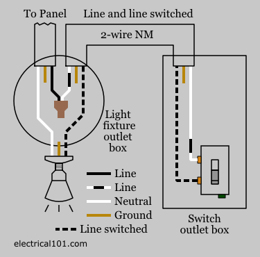
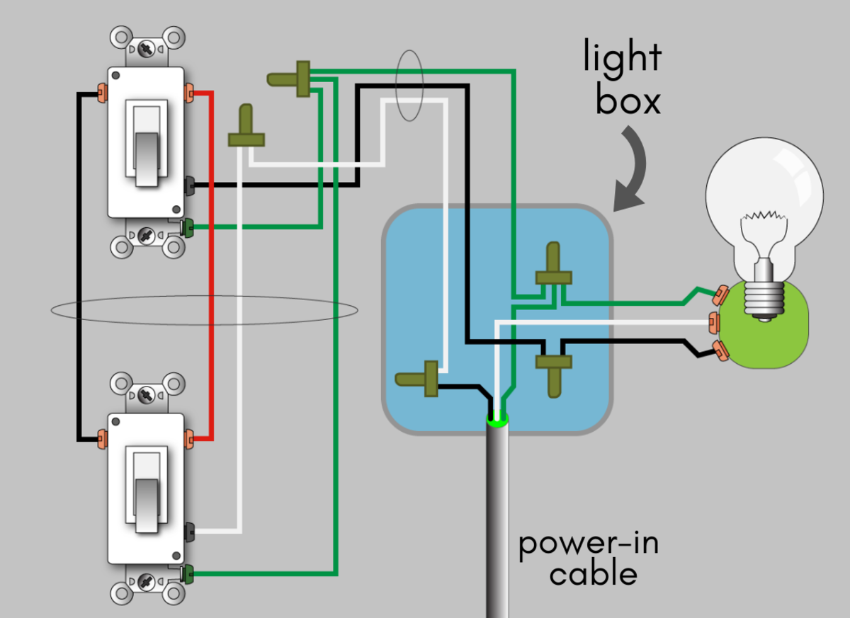
When the electrical source originates at a light fixture and is controlled from a remote location a switch loop is. Wiring a switch loop.
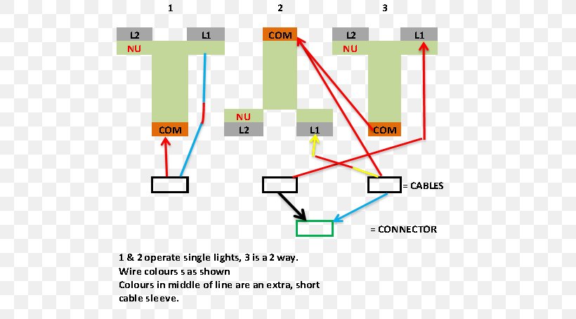
Light Switch Wiring Diagram Electrical Wires Amp Cable
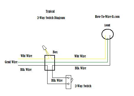
In line light switch wiring diagram. With nm cable the wire colors for travelers will be black and red using 3 wire cable. In this gfci outlet wiring and installation diagram the combo switch outlet spst single way switch and ordinary outlet is connected to the load side of gfci. Basic electricians pouch of hand tools and a voltage tester. Wiring a plug electrical diagram electrical wiring diagram electrical work electrical projects electrical switches electrical installation electrical outlets 3 way switch wiring. The power enters the ceiling light electrical box and branches off to the single pole wall switch using a three conductor cable. Wiring a single pole light switch.
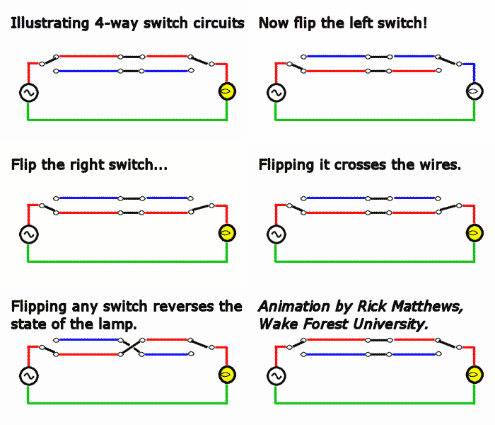
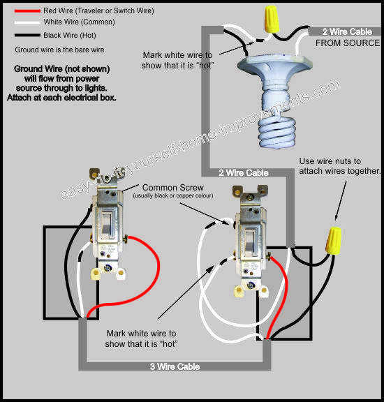
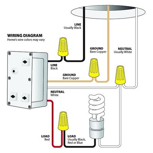
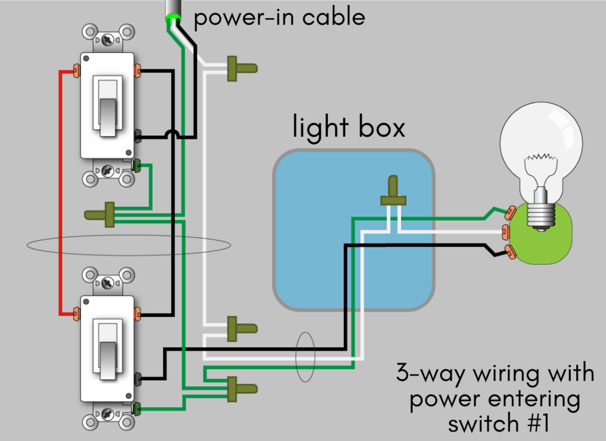
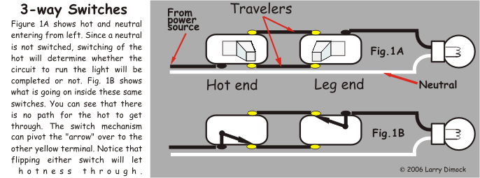
3 way switch wiring diagram. The colors will vary depending on whether nm cable or conduit was used. Also included are wiring arrangements for multiple light fixtures controlled by one switch two switches on one box and a split receptacle controlled by two switches. There is no way we can anticipate every situation and we do our best to inform of any risks for. 3 way switch wiring diagram light fixture between switches. This page contains wiring diagrams for household light switches and includes.
The toggle switch in the combo switch outlet controls the first light bulb while the single way switch controls the second bulb. Wiring light switches electrical project skill level. This site is merely a collection of how some people do home improvements. Line voltage enters the first 3 way switch outlet box light fixture is located between switch boxes. Here are a few that may be of interest. Looking for a 3 way switch wiring diagram.
Wood shop projects diy projects cool new gadgets creation crafts carpentry. Hey doing it yourself is great but if you are unsure of the advice given or the methods in which to job is done dont do it. If you are using a plastic switch the earth wires will need to be connected to the terminal in the terminal box as shown above because there are no earth terminals on plastic switches. The photo above depicts the wiring diagram of a ceiling light and light switch with the power from the circuit breaker panel. It means all the connected loads to the load terminals of gfci are protected. Depends on personal level of experience ability to work with.
3 way switch diagram multiple lights between switches fantazs laipa home electricity. A switch loop single pole switches light dimmer and a few choices for wiring a outlet switch combo device. In short all the loads is gfci protected. Click here to learn more about home electrical wiring more about wiring light switches. Wiring diagram of a ceiling light to a light switch using 3 conductor cable to the switch. The red wire from the feed cable is connected to the top terminal the red wire going to the light is connected to the bottom terminal the black wires from both cables are connected together in a plastic terminal block and the earth wires are connected to the earth terminal.
There is no standard for wire colors on 3 way switch travelers. Wiring diagrams for light switches wiring 3 way switches wiring 4 way switches wiring dimmer switches how to make your own light fixturesand much more. No longer allowed after 2011 nec if no neutral wire in switch boxes 3 way switch wire colors. This light switch wiring diagram page will help you to master one of the most basic do it yourself projects around your house.
