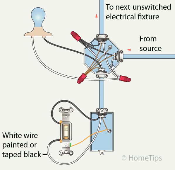
Mark the white wire at each end with black tape or black paint to indicate it is hot. 1a this is the most common loop in wiring arrangement you are likely to see.
Light Switch Wiring Diagrams Do It Yourself Help Com
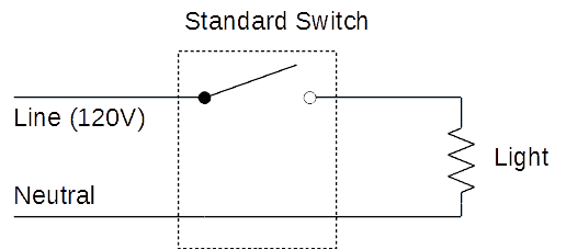
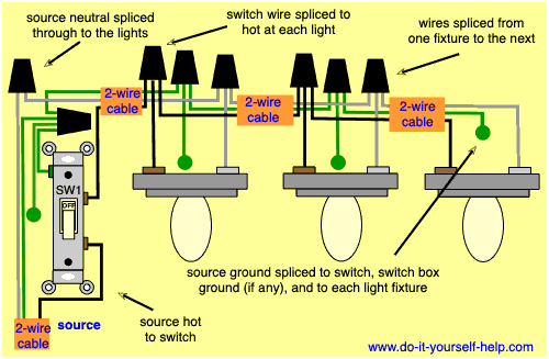
Light switch loop wiring diagram. Wiring a single pole light switch. Hey doing it yourself is great but if you are unsure of the advice given or the methods in which to job is done dont do it. Wrapping the wire clockwise when wiring a light switch ensures that the loop on the end of the wire will tend to close when the screw is tightened. This site is merely. The source is at sw1 and 2 wire cable runs from there to the fixtures. The source is at the outlet and a switch loop is added to a new switch.
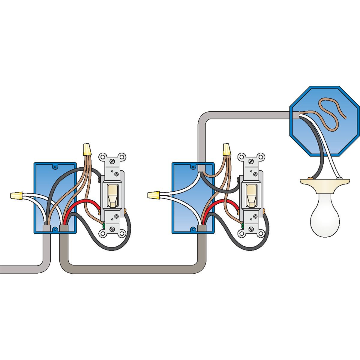
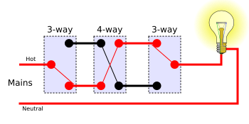
It shows three cables. The hot source wire is removed from the receptacle and spliced to the red wire running to the switch. Just click the wiring diagrams. This diagram illustrates wiring for one switch to control 2 or more lights. This 3 way light switch wiring diagram shows how to do the light switch wiring and the light when the power is coming to the light fixture. How to wire a gfci and outlet to a light switch.
The hot and neutral terminals on each fixture are spliced with a pigtail to the circuit wires which then continue on to the next light. This shows wiring a light switch when the power comes into the light outlet first. If you put the loop over the screw in the counterclockwise direction tightening the screw will force the loop open and could create a loose connection. The black hot wire connects to the far right switchs common terminal. This light switch wiring diagram page will help you to master one of the most basic do it yourself projects around your house. This wiring diagram illustrates adding wiring for a light switch to control an existing wall outlet.
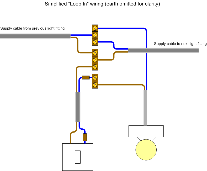
The light cable goes to the light fitting. To make a switch loop connect the incoming hot black wire to the white neutral wire that runs to the switch. Fully explained wiring instructions complete with a picture series of an installation and wiring diagrams can be found here in the gfi and light switch area here in this website. The black wire from the switch connects to the hot on the receptacle. Red and blue wires link traveler terminals of both switches. There will only be three wires at the light live neutral and earth.
Questions about wiring switches. One cable lne either from the mains board or the last ceiling rose one cable lne out to the next ceiling rose and one cable lsl e that goes to the wall or pull switch within that room. The principle is exactly the same as when looping at the ceiling rose or using a junction box. The out cable continues to the next light. The old method of a 2 wire drop is explained along with the current code requirements of using a 3 wire cable. The in cable supplies power from the previous light or consumer unit.
Next the incoming white neutral wire is attached to the light fixture as usual and the black wire from the switch is connected to the light fixture. In this diagram power enters the fixture box. Loop at the switch.


