Rv power converter wiring diagram rv power converter wiring diagram rv power inverter wiring diagram every electrical structure consists of various distinct parts. How to wire an rv power converter step 1.
Electrical Breakers And Fuses
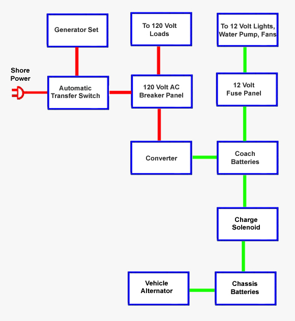
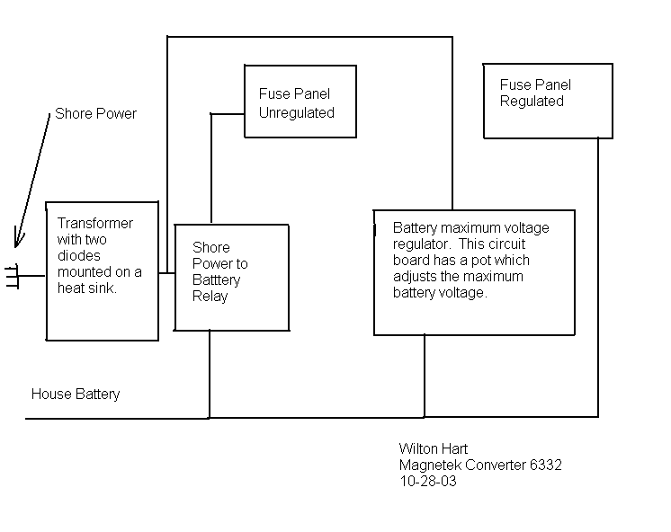
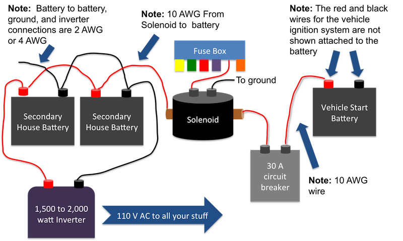
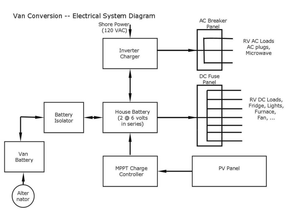
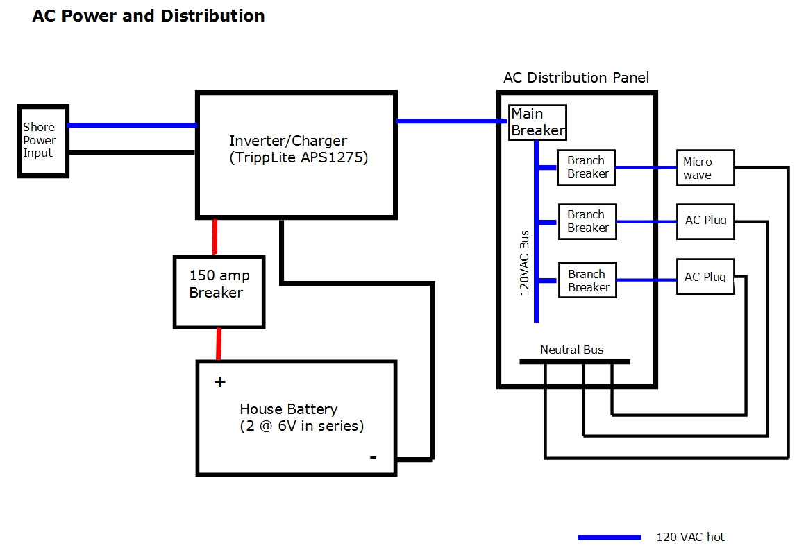
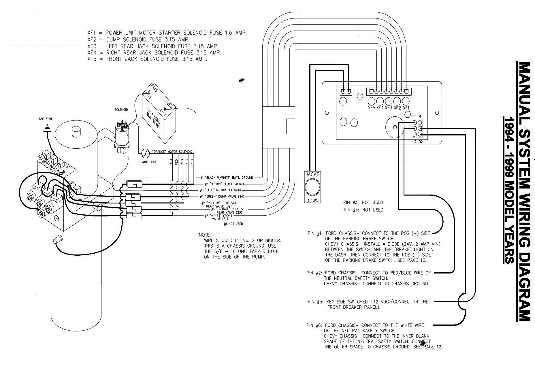
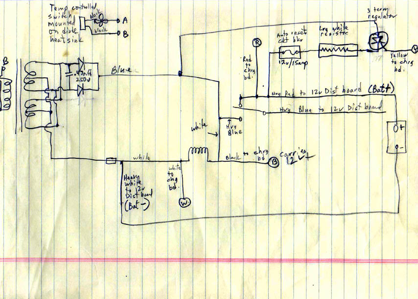
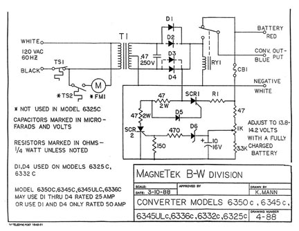
Rv converter wiring schematic. A wiring diagram is a simplified conventional photographic representation of an electrical circuit. Disconnected your rv from shore power andor switch off your generator. Collection of rv inverter charger wiring diagram. It shows the components of the circuit as simplified shapes and the power as well as signal connections between the devices. Honestly we also have been remarked that rv inverter wiring diagram is being just about the most popular field at this moment. Below is a rv electric wiring diagram or schematic including the converter and inverter for a generic rv.
Rv electrical diagram wiring schematic understanding you campers electrical wiring can be very confusing. A power converter typically has four terminals. Use the rv electrical diagram we made below to get an understanding of what powers what and to learn how an rv electrical system works. Types of rv electricity there are 2 main types of sources of rv electricity within your rv 12 volt dc and 120 volt ac same as 110 volt just like your stick brick for our purposes. Dual rv battery wiring diagram dual rv battery wiring diagram inside rv inverter wiring diagram image size 771 x 770 px and to view image details please click the image. In fact that is probably an understatement.
Types of rv electricity there are 2 main types of sources of rv electricity within your rv 12 volt dc and volt ac same as volt just like your stick brick for our purposes. Each component should be placed and connected with other parts in specific manner. So we attempted to uncover some terrific rv inverter wiring diagram graphic to. Here is a picture gallery about rv power converter wiring diagram complete with the description of the image please find the image you need. Consult the instructions provided with the device and wire it. Assortment of rv converter wiring schematic.
A wiring diagram is a simplified standard pictorial depiction of an electrical circuit. Now most electrical experts will agree that the converter that comes from the factory in most rvs while functional is not the best method for charging your house batteries. Trace those wires. Otherwise the structure will not function as it should be. This appearsbelow is a rv electric wiring diagram or schematic including the converter and inverter for a generic rv. Rv power converter wiring diagram on 2006fleetwooddiagramgif within rv power converter wiring diagram image size 1024 x 599 px and to view image details please click the image.
The diagram below shows a typical rv electrical system set up with a converter. Loosen the clamp holding the ground. It reveals the components of the circuit as simplified forms as well as the power and signal links between the devices.

