Some single phase induction motors are also called squirrel cage motors because of the rotors similarity to. A copper conductor isolates the shaded portion of the pole.
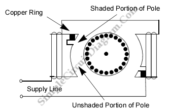
Shaded Pole Ac Induction Motor Simple Circuit Diagram
Shaded pole motor wiring diagram. Construction of shaded pole induction motor. A common single phase motor is the shaded pole motor which is used in devices requiring lower torque such as electric fans microwave ovens and other small household appliances. A shaded pole motor may be of 2 poles or 4 poles. Ensure that pwm type motors are connected to the control pwm terminal blocks and vdc motors to the vdc. And manufacturers wiring schematics also use diagrams b and c to ensure a positive troubleshoot ing application. The figures in this article also show a 2 pole motor.
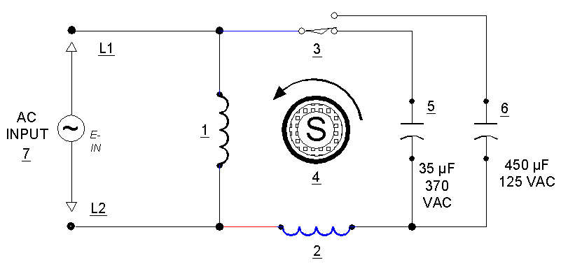
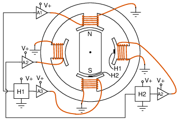
Applications of the shaded pole induction motor. Shaded pole motor wiring diagram the shaded pole motor is the original type of ac single phase induction motor dating back to at least as early as a shaded pole motor is a small. Construction of shaded pole induction motor. Part of each pole is encircled by a copper coil or strap. A shaded pole motor and its schematic diagram are shown in the figures above. Shaded pole motor wiring diagram.
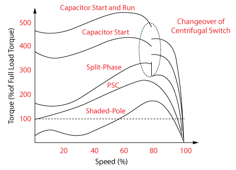
Bracket from the evaporator to replace the shaded pole motor with the new ecm motor. Working of shaded pole induction motor. The various applications of the shaded poles motor are as follows they are suitable for small devices like relays and. The stator poles are equipped with an additional winding in each corner called a shade winding as shown in fig4. Characteristics of shaded pole motors. Here we are considering a 2 pole shaded pole motor.
A shaded pole motor includes a winding which is placed around the pole part that holds up the magnetic field phase. Refer back to this diagram as the operational requirements of the single phase motor are discussed. In the salient pole configuration machine the magnetic field pole can be generated produced with a winding wound approximately under the pole face. In the non salient pole configuration the winding can be dispersed within slots of pole face. Mount the ecm motor with the wire harness in the down position. Read here to know about the shaded pole motors their constructional features working and how they are used in starting of single phase induction motors.
The field rotates from the unshaded portion to the shaded portion of the motor. Reserves the right to change any specifications or data without notice. The pole structure of the shaded pole motor enables the development of a rotating magnetic field by delaying the buildup of magnetic flux. These windings have no electrical connection for starting but uses induced current to make a rotating magnetic field. Figure 17 3 shows a very basic one line diagram of the single phase motor. In this motor small single turn copper shading coils create the moving magnetic field.
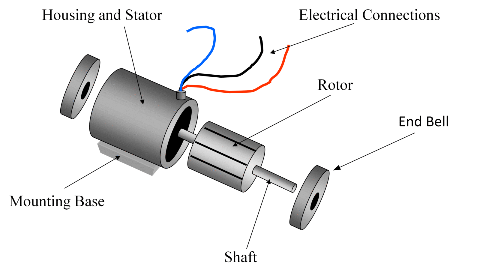
The single phase induction motor is much the same in construction as the three phase motor. Construction of shaded pole induction motor. Shaded pole motor is one of the types of single phase induction motors which are used for producing a rotating stator flux in order to make the single phase induction motor a self starting onelet us discuss the constructional details diagrams and working of shaded pole motors in detail. The rotating magnetic field develops the starting torque in the motor. The induced current in the strap opposes the change of flux through the coil lenzs law so that the maximum field intensity moves across the pole face on each cycle. Some kinds of motors include conductors with thicker metal like sheets of metal otherwise bars generally copper otherwise aluminum.
As there is time and space displacement between the two fluxes the rotating magnetic field induces in the coil. The connection diagram of the shaded pole motor is shown below. Call ebm industries at 860 674 1515 fax 860 674 8536 e mail. Connect the ecm motor speed control signal negative wht wire and positive blk wire leads to the supplied or any 18awg wire and connect to the control negative and positive pwm or vdc terminals per wiring diagram on page 7.
