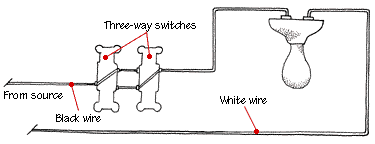
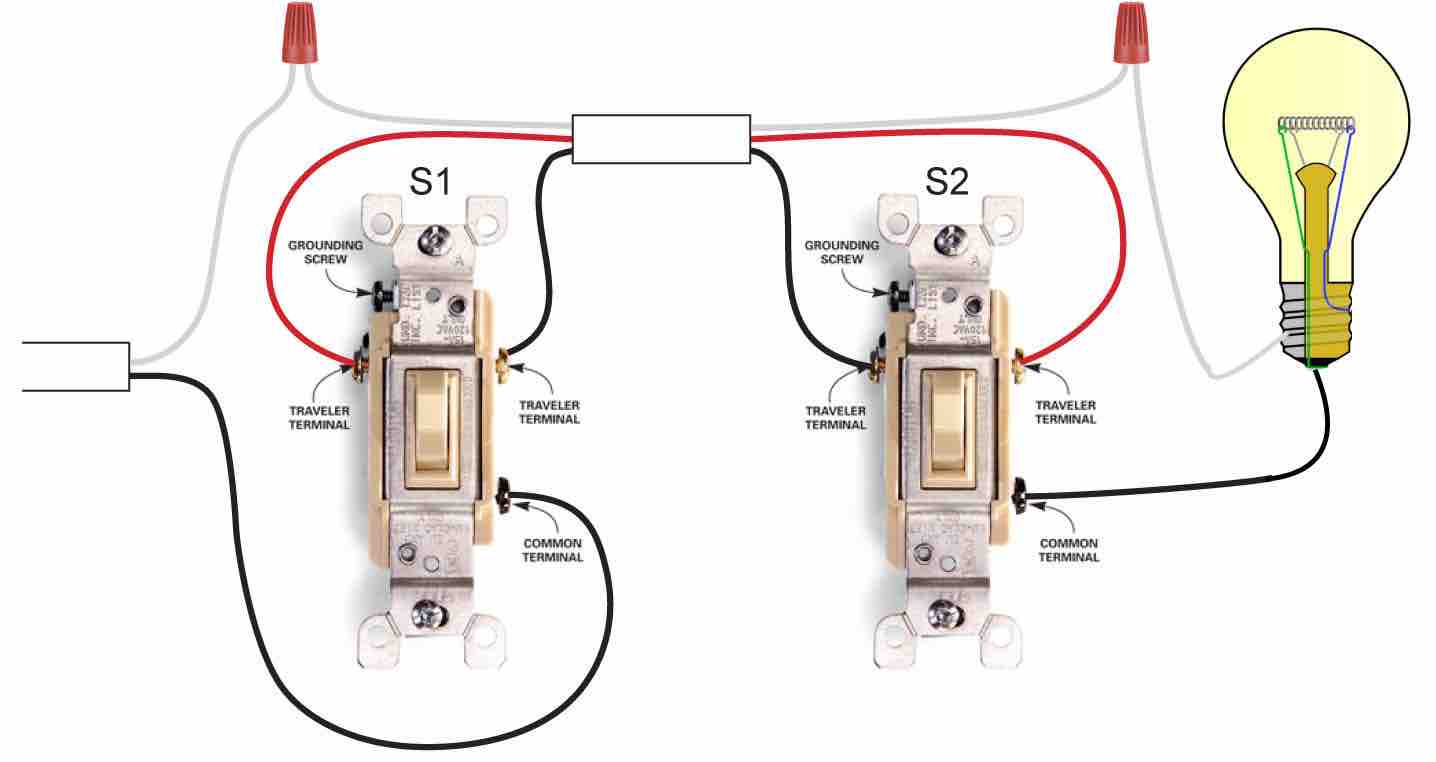
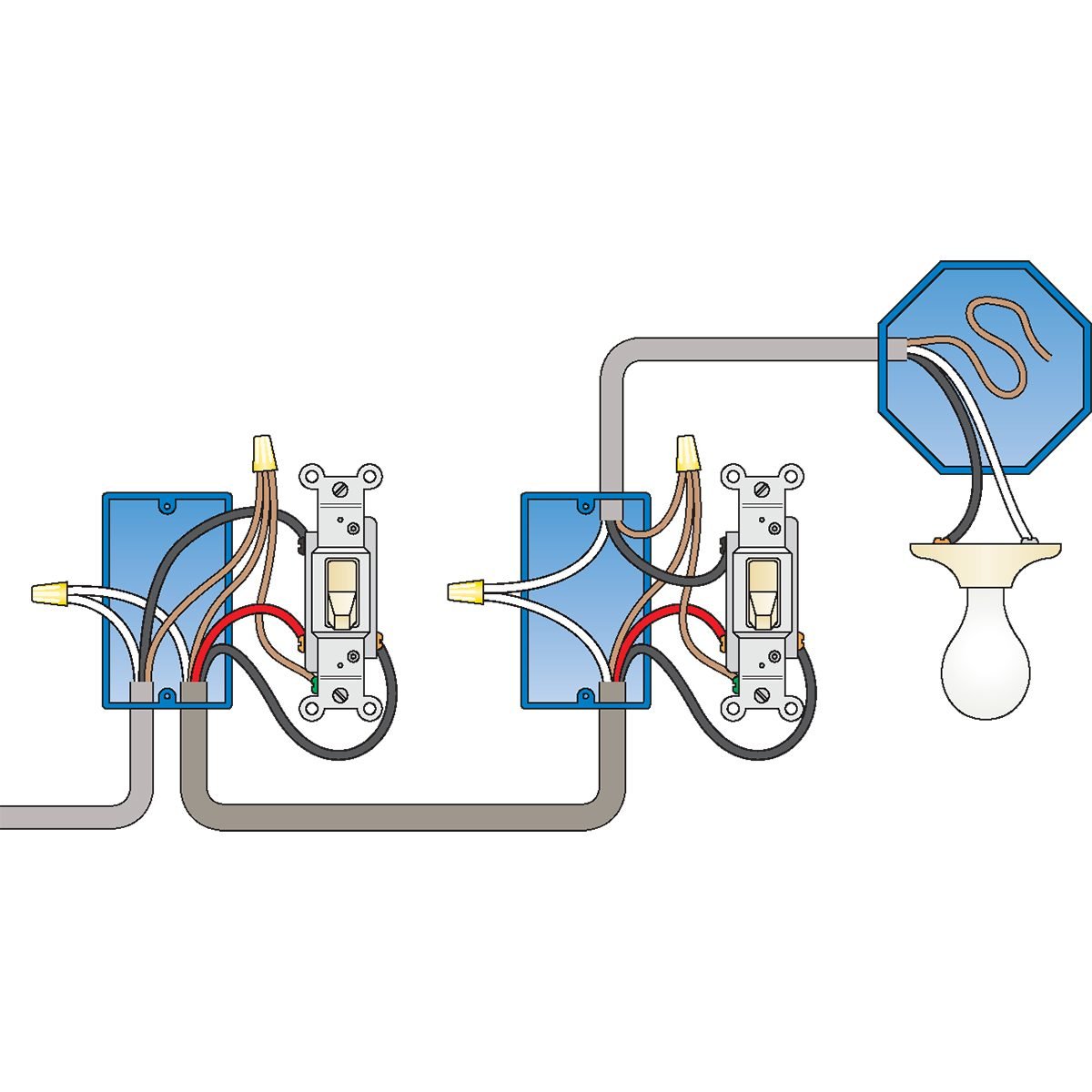
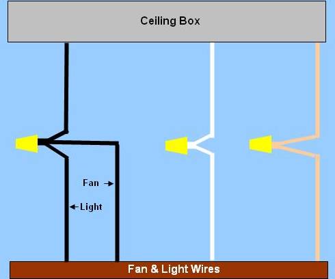
3 way switch wiring diagram. Power coming in.
Light Switch Wiring Diagrams Do It Yourself Help Com
Wall switch wiring diagram. An electrical wiring diagram can be as simple as a diagram showing how to install a new switch in your hallway or as complex as the complete electrical blueprint for your new home or home improvement project. After you have pulled your switch out from the wall the wires in the box and connecting to the switch should look like one of the following. This wiring diagram illustrates adding wiring for a light switch to control an existing wall outlet. Duplex receptacle outlets are made for feed through of the power from one. Confirm the electricity is off at the spot. Wood shop projects diy projects cool new gadgets creation crafts carpentry tools diy welding milwaukee tools construction tools garage tools.
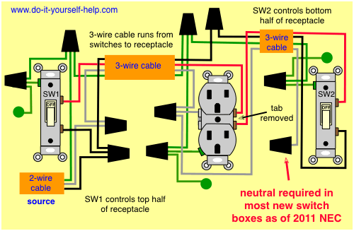
Outlets are split wired so that the top half of the receptacle is live all of the time and the bottom of the receptacle is controlled by the wall switch. Featuring wiring diagrams for single pole wall switches commonly used in the home. Get these ultimate bits for 50 off today. Common applications include ceiling or hallway light switches. You can avoid costly mistakes. The source is at the outlet and a switch loop is added to a new switch.
Basic 2 way circuit power coming in at switch. The two conductor cable from the ceiling box to the light. Pick a single pole light switch for most applications. Made with premium 6542 hss carbide with a reinforced head to prevent cracking our twist drill bit sets are made of an impossibly hard durable alloy. Basic 2 way circuit power coming in at light. Circuit electrical wiring enters the switch box the black wire power in source attaches to one of the switch screw terminals fixture wiring exits the switch box the black wire power out wiring attaches to the.
Choices of light switch wiring diagrams the two conductor wiring diagram at the top of this page. Home electrical wiring diagrams are an important tool for completing your electrical projects. Turn off the electricity carefully. The black wire from the switch connects to the hot on the receptacle. Lets look at the following 2 way switch diagrams to see which type of circuit scenario you have. Looking for a 3 way switch wiring diagram.
Multiple receptacle outlets can be connected. Locate your circuit breaker box and the circuit breaker specific to the switch to. The hot source wire is removed from the receptacle and spliced to the red wire running to the switch. If a ceiling fan. Wiring a switch to a wall outlet here a receptacle outlet is controlled with a single pole switch. When wiring a 2 way switch circuit all youre really doing is controlling the power flow switching offon to the load a light lamp.
In this diagram 2 wire cable runs between sw1 and the outlet. Here are a few that may be of interest. This is commonly used to turn a table lamp on and off when entering a room. Switched receptacle outlet wiring diagram depicting the electrical power feeding into an electrical receptacle box and then going to a switch and to another receptacle.
