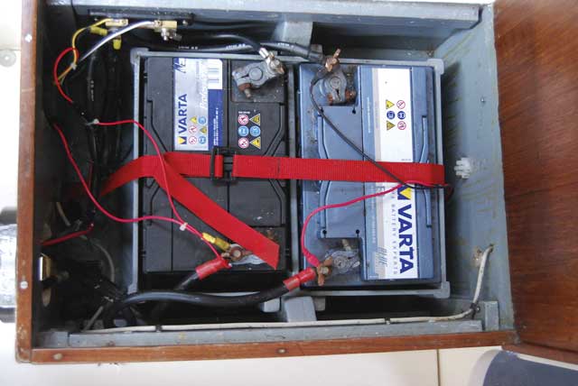
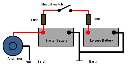
Notice the fuse shown this needs to be circuit protected with an inline fuse like this one. When you do wire your alternator direct to the house bank please consider installing an alternator service disconnect switch.
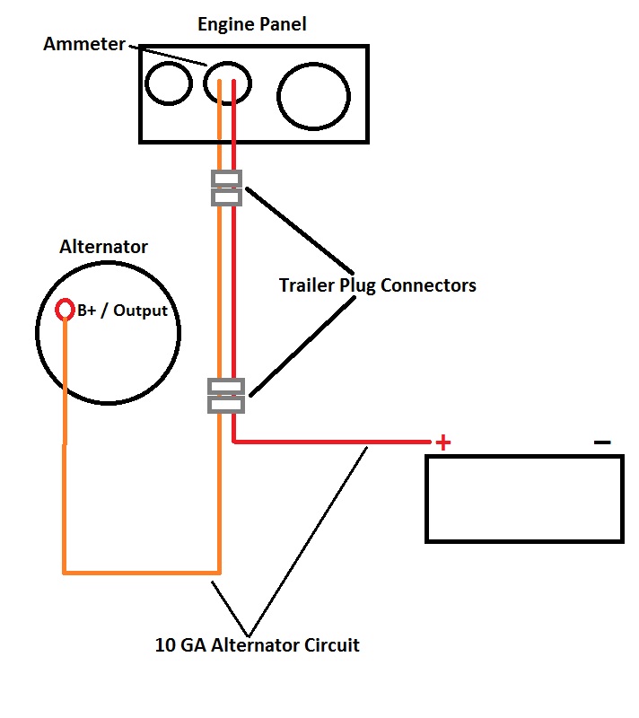
Early Universal Engine Charging Circuit Photo Compass
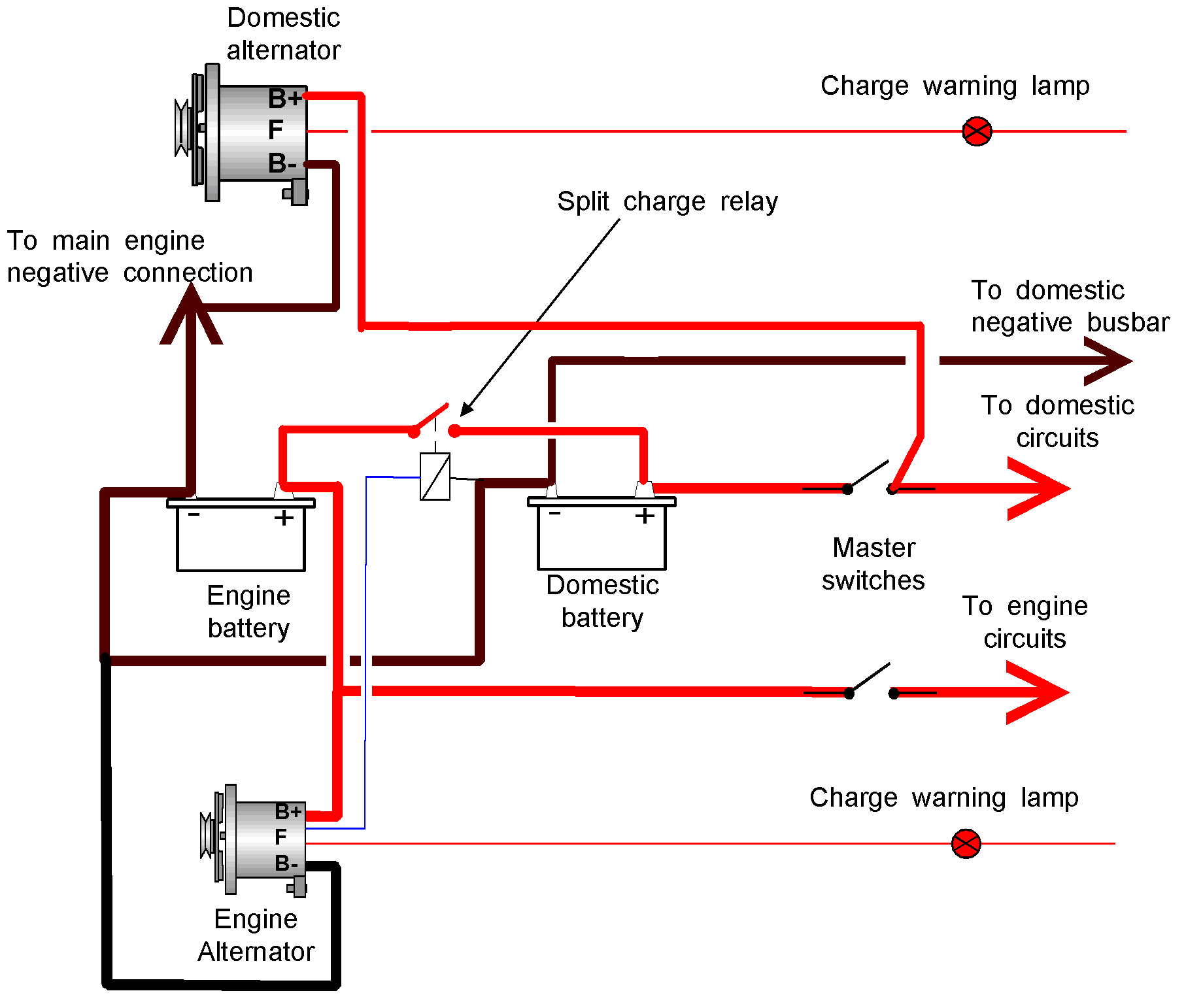
Wiring alternator to battery bank. This way even if your battery switch is off if your boat starts filling with water the pump will still kick on. These fuses are there to protect the acr positive wiring from the battery bank should they short to ground. To connect batteries in a series use jumper wire to connect the negative terminal of the first battery to the positive terminal of the second battery. I run the fiesta alternator from the flywheel of a 1942 lister dk and the. Multiple dual circuit plus battery switches can be used to switch systems with multiple battery banks. Click on the links below to view schematic diagrams for 2 3 and 4 battery bank applications.
Id rather have a dead battery than a swamped boat. Multiple battery bank solutions. Your battery bank is only 50 charged when your isolator relay connects it to the alternator and starting battery so its chart looks like this. A service disconnect switch is a switch placed visibly in the engine space and clearly labeled so a service technician can isolate the alternator from the battery bank while working on the engine without having to remove a fuse to do so. The shape is really similar but the currents are much bigger because the bank is bigger and the voltages are lower because the bank is half discharged. In order to share an alternator with more than one battery we need 1 a parallel battery switch eg.
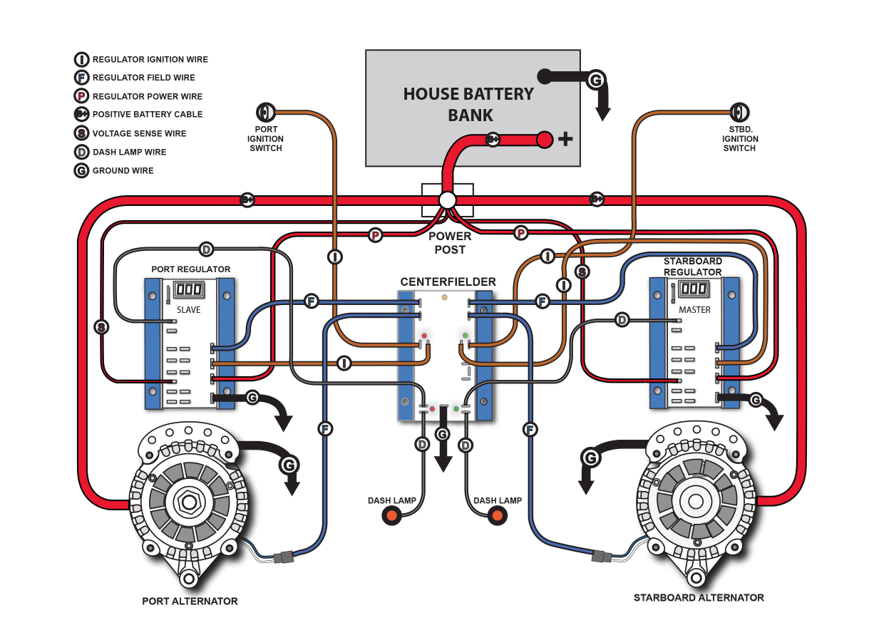
Usualy there are 4 wires one wire is from the casing which goes to the negative terminal of the battery then out of the other 3 wires one is the field wire which you should connect to positive but make sure you put a basic on off switch turn switch on when starting alternator turn off once running and leve off when not in use. Use another set of cables to connect the open positive and negative terminals to your application. Off 1 2 both 2 a battery combiner or 3 a battery isolator. Vsrs come into their own when a small inboard or outboard engine is used which has combined starter motor and alternator wires to the battery. To make matters even more challenging for recharging multiple battery banks alternators are single output devices and therefore are meant to only recharge one battery bank. As can be seen in the image above an acr is wired between the positive terminals of each battery bank with the only thing in its path being the fuses located within 7 of each positive battery terminal.
In this case a diode system will only let the current flow one way whereas a vsr will allow both charging and starting with only one set of wiring. This is the most basic way to connect an alternator to make a charging set or to run an inverter from a stationary engine. Im also showing the negative return wiring for the bilge pump in this step. The other two wires go to the positive terminal of batery if.







.jpg.445a8ba9ff2c0b9e683c64448a82e897.jpg)
