All 3 wire submersible pumps from 13 up to 1 hp utilize a qd control box to start the pump. So you would go from panel to disconnect if required and then to the pressure switch and then to the control box.

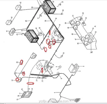
9337806 Control Box Wires 5001380 Working Lamp 5000246 Fan 5003305 Oil Pressure Sensor 9302787 Plate 5000139 Switch View Control Box Wires
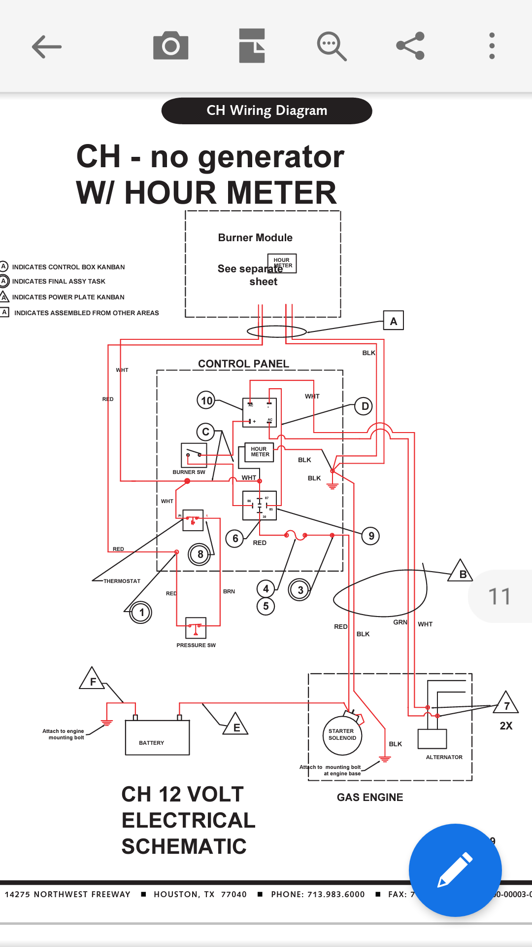
Wiring pressure switch to control box. The box is the same one that was in place previously i took the old one in. In this video we review how pressure switches work in turning pumps on and off and discuss how to wire a pressure switch. Collection of well pump pressure switch wiring diagram. How to wire a pressure switch for a water pump. Switch off the power that feeds the pump circuit while you are wiring the switch. This video shows wiring a franklin submersible pump control box.
The third wire is attached to a start capacitor within the control box because larger motors need help when they first fire up. You can either switch off the circuit breaker or pull. Open the pressure switch wire box by removing the plastic or metal cover. Submersible pump control box wiring diagram water pump pressure switch wiring diagram fresh wonderful franklin submersible pump wiring diagram s. Generally there is a. Well pump pressure switch wiring diagram wiring diagram for pressure switch refrence well pump pressure switch wiring diagram new magnificent wiring.
The box is a franklin qd connect 2801054915 capasitor start 12 hp. How to wire a submersible pump controller. The box is a five wire connection black is main yellow motor leads and l2 redstart blue is l1. Leave the power off until youre ready to test the new. With the power off open the nearest tap usually a hose bib on the tank tee until the pressure gauge reads 0 psi then close it. Please note that at 113 the instructor says that the colors dont.
All of this so far would be 2 hots and a ground wire. Click on the image to enlarge and then save it to your. In this video chris shows you how to wire the franklin electric qd control box. Main goes to a control box which the capasitor is attaced to along with the l1. My problem comes in with the correct way to wire the pressure switch to the control box and then to the pump. The pump is a single phase 3 wire redblackyellow.
If it runs straight to the pressure switch it is a two wire. If the conduit runs into a control box before continuing to the water pressure switch chances are you have a three wire pump. You run that into the control box and run the 4 colored well pump wires out of the control box to the pump.


