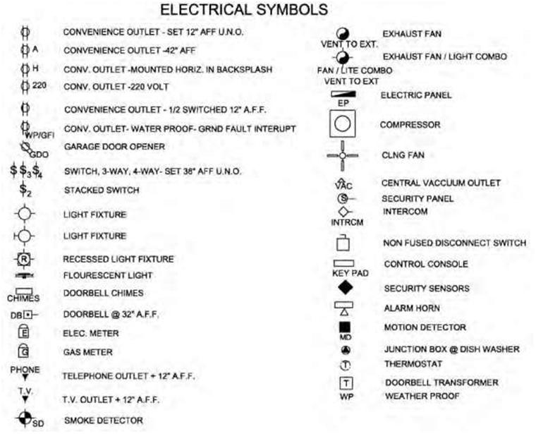
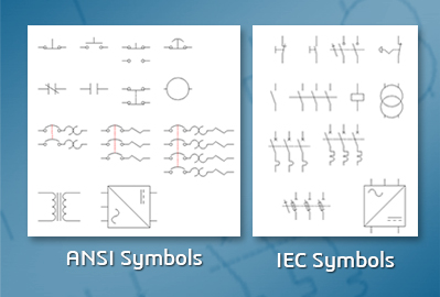
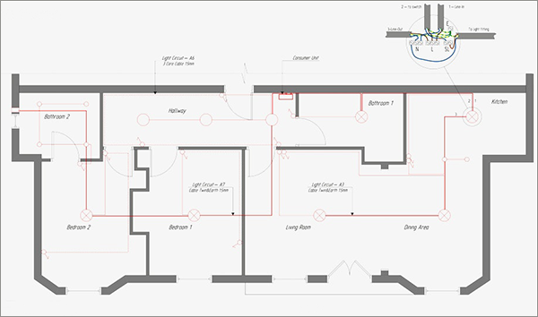
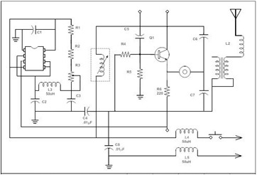
Below lists most commonly used electrical and electronic symbols that can help you get started quickly. Below is a figure showing the most often used residential electrical blueprint symbols.

5 Types Of Construction Drawings Used In Commercial
Commercial electrical blueprint symbols. Figure 1 4 but today most plans are created digitally using. Creation the plan of such kind lets you to. Computer aided de sign cad software tools. Though these standard symbols are simplifiedthe function descriptions can make you understand clearly. Electrical symbols virtually represent the components of electrical and electronic circuits. Landscaping shows landscaping views and irrigation.
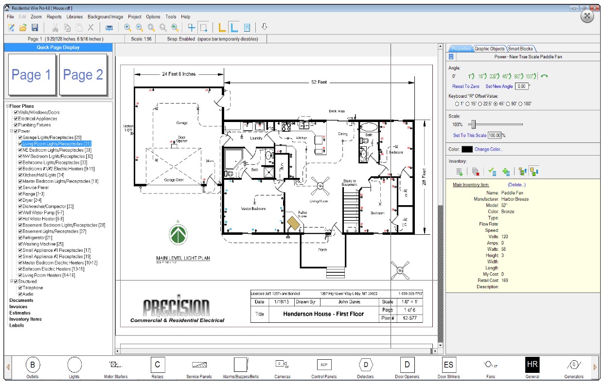
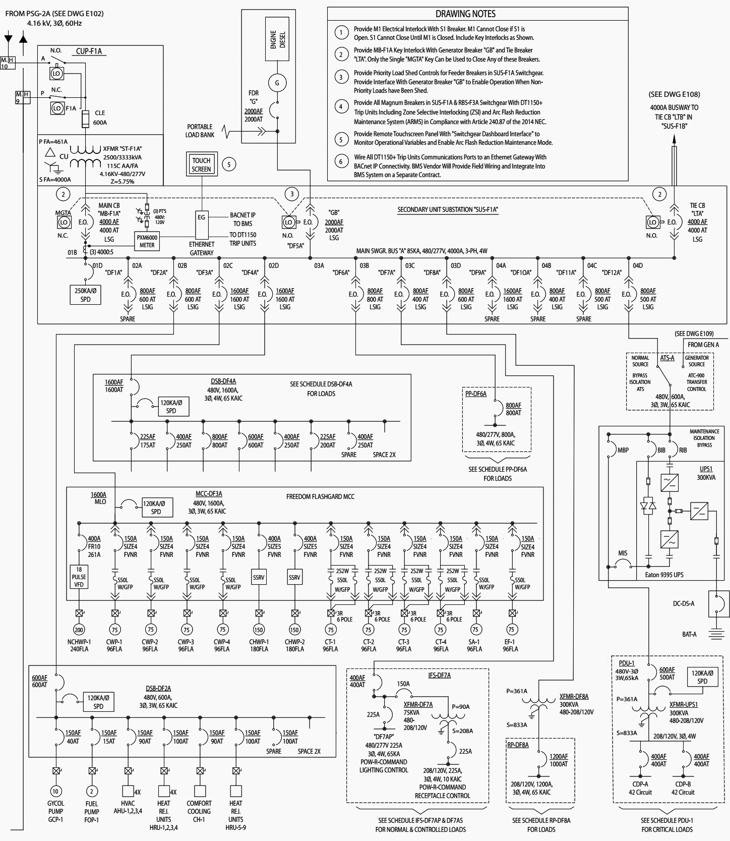
Because commercial and industrial buildings contain a number of electrical systems. The lists represent a good set of electrical symbols in that they are easy to draw easily interpreted by workers and sufficient for most applications. B different electrical systems such as power distrib ution luminaire voicedata fire alarm and security access control should be shown on separate plans if combining them on the same drawings would reduce clarity. Drawn blueprints see. For other residential symbols see our blueprint symbols page. The most common size sheets are architec tural d sheets which are 24 in.
Many electrical symbols are used to show the desired lighting arrangement. C electrical plans are generally drawn to scale. Architectural indicates the master view and details of floor plans. The electrical system for a small property would typically. Products solutions samples buy this site uses cookies. The electrical symbols be drawn darker than the back ground drawing showing the building structure andor other systems.
The most commonly used electrical blueprint symbols including plug outlets switches lights and other special symbols such as door bells and smoke detectors are shown in the figure below. Hundreds of blueprint symbols are used and without any strict international standards there may be some minor variations to some of them depending on geographical location. Switch symbols are usually placed perpendicular to the wall and read from the right side or bottom of the sheet. A complete set of blueprints for an entire construction project includes but is not limited to the following types. Electrical blueprint symbols glossary. Symbols commonly used in electrical shematic drawings single pole switch three way switch four way switch dimmer switch combo 2 single pole switches combo single pole switch and receptacle incandescent light duplex receptacle split wired receptacle gfci receptacle always include the load and line side this product was funded by a.
When printed digital plans are typi cally produced on standard sized architectural plan sheets. How to use appliances symbols for building plan. This article shows many of the frequently used electrical symbols for drawing electrical diagrams. Here is a standard wiring symbol legend showing a detailed documentation of common symbols that are used in wiring diagrams home wiring plans and electrical wiring blueprints. One of the obligatory documents that is included to design project of home appartment office center or any other premise is the plan of arrangement of different appliances and home appliances. This product is copyrighted by the institution that created it and is intended for individual organizational non commercial use only.
Ground a connection to the. Explanations for common household electrical items such as three way switches and. By continuing to browse the conceptdraw site you are agreeing to our use of site cookies. Figure 87 shows two lists of electrical symbols currently in use on most electrical drawings. Commercial electrical blueprint symbols. Civil shows topographic views of all exterior surroundings.
However graphic symbols indicate only the approxi mate locations of electrical equipment. Digitized plans are easier to revise and transmit than those drawn with pen and pencil. Wiring diagrams use simplified symbols to represent switches lights outlets etc.
