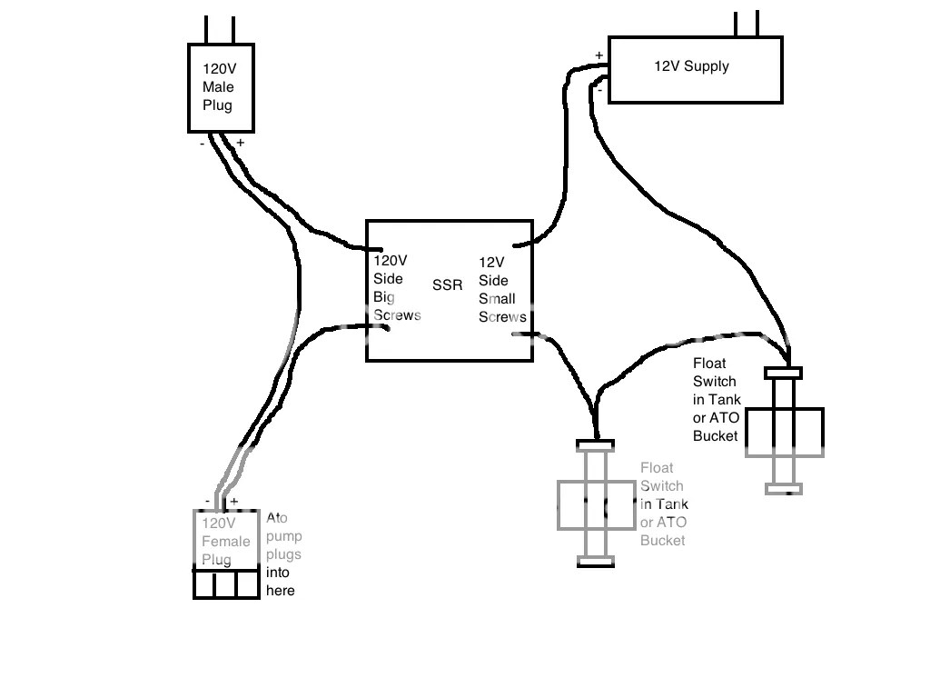
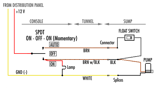
If a receptacle outlet will be installed then a weather proof cover must be installed to offer protection from the weather even while the sump pump is plugged in. Collection of 3 wire submersible pump wiring diagram.
Electronic Hi Lo Pump Switch Automatic Hi Low Float Switch
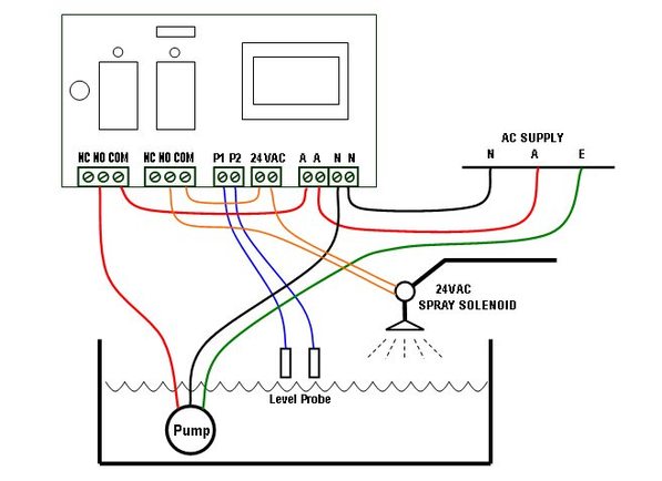
Sump pump wiring diagram. Check out this sump pump diagram for more details. A wiring diagram is a streamlined conventional pictorial depiction of an electrical circuit. An accurate panel wiring diagram. A means of disconnect for the sump pump must be located within sight and readily accessible. A set of jumper wires. Plug in ready wiring makes installation.
Most of those involve commercial grade pedestal sump pump installation. This is very subjective because there are options for high end pump that are in the 2k range. Pump that has a heavy duty cast iron housing the cast iron dissipates heat better than other materials a ceramic shaft a true solid state. High end sump pump. Electrical wiring for a sump pump circuit. It reveals the elements of the circuit as simplified shapes and also the power as well as signal links between the tools.
The sump pump should be protected by either a gfci outlet or a gfci circuit breaker. For this discussion and this price range youll probably get a ½ hp. Detailed step by step video of how to wire a septic pump and alarm system. A wiring diagram is a streamlined traditional photographic representation of an electrical circuit. Collection of sump pump wiring diagram. Edw wd s economy duplex sump pump control.
This manual is. Check motor wiring diagram. If over 100º f overload may be tripping on external heat. Provide adequate ventilation or move pump. Reconnect for proper voltage as per wiring diagram. Always observe local codes that may differ.
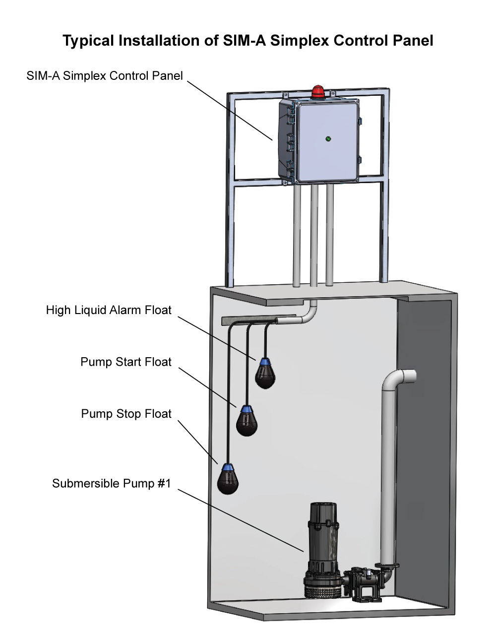
Check air temperature where pump is located. Of the three bilge pump switches the only one thats not extremely simple is the backlit automanual bilge pump switch. Simplex sump pump control panel wiring diagram simplex s series pump control panels are ideal for pressure sewer or onsite orenco s1 series simplex control panel wiring diagram. In the right hand diagram you can see how the backfeed from the float switch might come back up the manual line and. As far as i am aware this is fully adequate to satisfy nec codes. It reveals the components of the circuit as streamlined forms and the power and also signal connections between the gadgets.
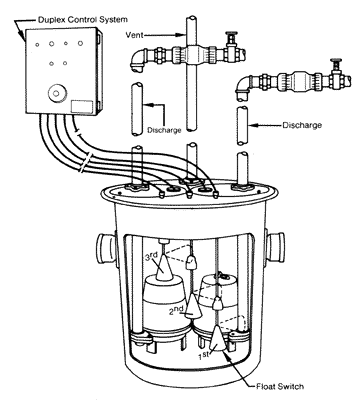
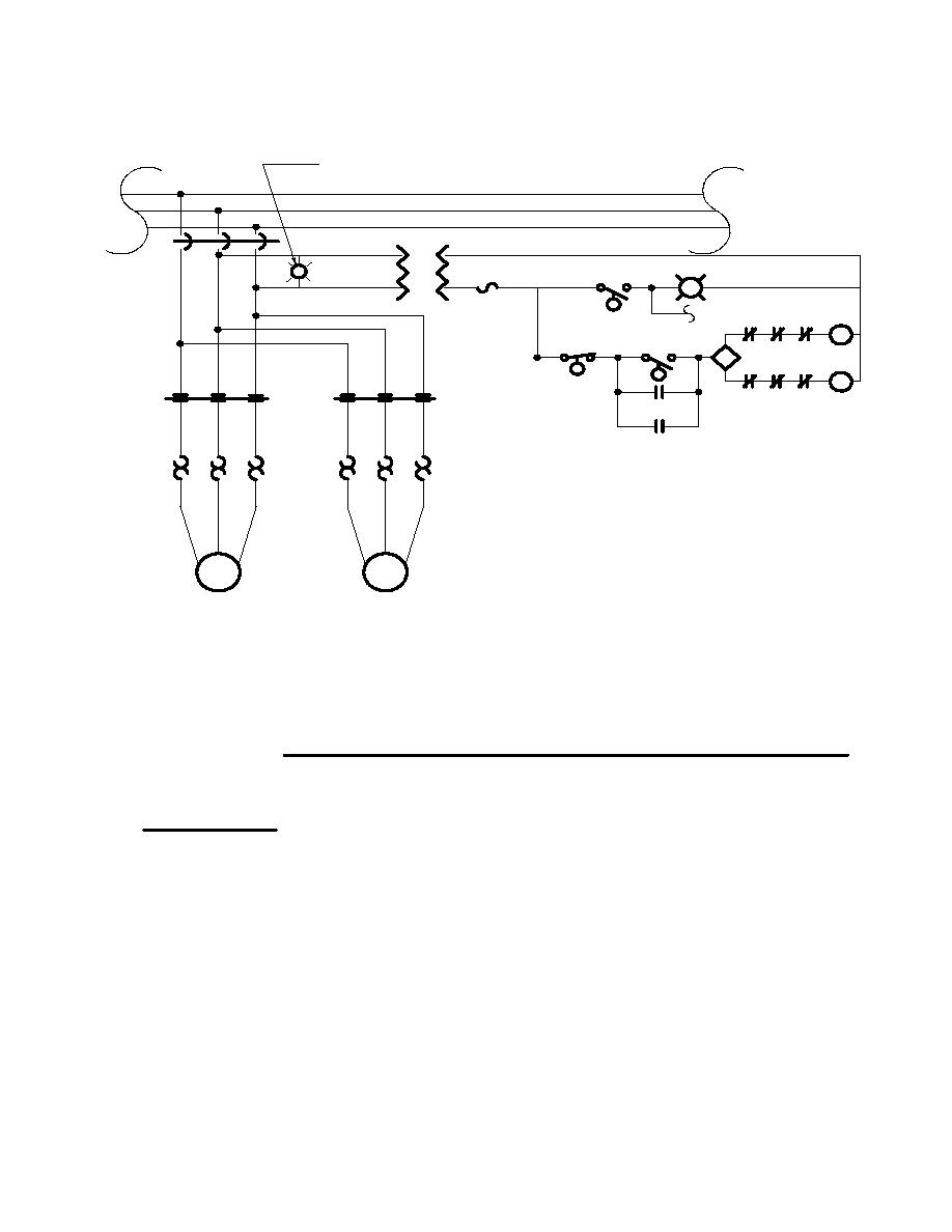
3 backlit bilge rocker switch wiring diagram. Learn more about how our awesome backlit switches work here even that one is still pretty straight forward though here are some diagrams that show the single jumper required on the back of the switch. Collection of sump pump wiring diagram. Volt or volt 60 hz single phase these 12 hp pumps come with a 15 electrical. The duplex control provides alternating operation of two volt pumps. Submersible sump pumps by zoeller are great for pumping out the water in your steel handles and guards have automatic reset thermal overload protection can view 50 series pump performance curve chart view 50 series pump.
Continuous operation at very low pressure places heavy. The wire size that should be used for the 20 amp septic sump pump circuit should be 12 gauge. Voltage ohm and for single phase systems. It shows the elements of the circuit as simplified forms and also the power as well as signal links between the devices. More about sump. Prolonged low pressure delivery.
Motor winding resistance values. Pump performance and. A wiring diagram is a simplified conventional photographic representation of an electrical circuit.
